Seems like the losses on a horn will have to be an educated guess, maybe I will build a much smaller downscaled version of the two enclosures based on a 5" driver etc to see if my predictions are close before going ahead and building something largerhave a look at my question and the following answer from david here (post 12555): https://www.diyaudio.com/community/threads/hornresp.119854/page-628#post-6859912
I will also search up other peoples hornresp vs real world measurements to hopefully make my guess more accurate
Hmm, you want a 'slight upwards curve towards 20hz so it sounds flat to my ear', so historically an angled shelf vent was used: https://www.diyaudio.com/community/threads/next-project-fe206en-cabinet.348930/post-6070776
That, or do like the horn pioneers did re short horn design [my understanding from experience, no docs to prove it], i.e. design a full size one in whatever pi space and 'slice' the appropriate BW out of it, which for the bass usually means that just an angled shelf in a square/rectangular box = parabolic flare factor shelf vent in the article.
Offset driver vs Tapped horn anomaly, could someone explain why this happens?
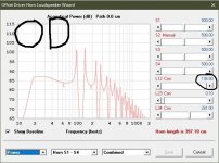
Why does changing from OD to TH with the driver a theoretical 0.1cm down the throat change my required offset by so much? yet changing acoustic path between driver and mouth on OD makes no difference? I feel like there shouldn't be much of a difference between TH being 0.1cm in the throat and OD being 1cm from mouth
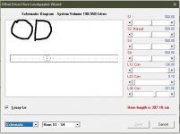
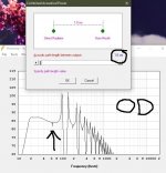
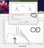
capture 1/2 shows the OD
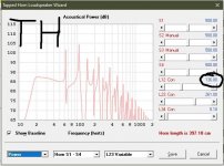
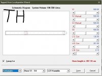
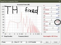
capture 3/4 shows TH with same offset but large peak appears at 60hz
capture 5 shows an 11cm adjustment to fix TH peak
capture 6/7 shows theres no difference changing acoustic path from 1cm to 100cm
Why does changing from OD to TH with the driver a theoretical 0.1cm down the throat change my required offset by so much? yet changing acoustic path between driver and mouth on OD makes no difference? I feel like there shouldn't be much of a difference between TH being 0.1cm in the throat and OD being 1cm from mouth
capture 1/2 shows the OD
capture 3/4 shows TH with same offset but large peak appears at 60hz
capture 5 shows an 11cm adjustment to fix TH peak
capture 6/7 shows theres no difference changing acoustic path from 1cm to 100cm
Attachments
If you look at the system models available in the Loudspeaker Wizard for OD and TH, you can see that the driver is loading horn segment 2 differently.Why does changing from OD to TH with the driver a theoretical 0.1cm down the throat change my required offset by so much? yet changing acoustic path between driver and mouth on OD makes no difference? I feel like there shouldn't be much of a difference between TH being 0.1cm in the throat and OD being 1cm from mouth
With OD:
- side1 of the driver is radiating into the air
- side2 of the driver is radiating into the horn between segments 1 and 2
- the acoustic path sets the distance for summation between the radiation from side1 and radiation from the exit of segment 2
- even with acoustic path set to 0, radiation from side1 is not modeled as radiating into the exit of segment 2
With TH:
- side1 of the driver is radiating into the horn between segments 1 and 2
- side2 of the driver is radiating into the horn between segments 2 and 3
- even with segment 3 set to a very small number, radiation into segment 2 still takes place.

What will happen if I terminate a 20hz bass horn at 1/2 wavelength with a perfect absorber? (Taking a measurement inside the horn just before the termination.)
Would it act like an infinite horn?
Would it act like a horn radiating into free space?
How do I model this in hornresp?
Would it act like an infinite horn?
Would it act like a horn radiating into free space?
How do I model this in hornresp?
Neither. The impedance at the horn mouth differs between the three cases.What will happen if I terminate a 20hz bass horn at 1/2 wavelength with a perfect absorber? (Taking a measurement inside the horn just before the termination.)
Would it act like an infinite horn?
Would it act like a horn radiating into free space?
How do I model this in hornresp?
What is a perfect absorber depends on the wave you want to absorb (plane, spherical, etc).
For an exponential horn, the termination that results in no reflected wave is an infinite exponential horn. You model this by connecting the horn to an infinite esponential horn of the same flare rate.
If you terminate it by a plane wave absorber (rho * c termination), it will act as an impedance transformer between the impedance of the absorber at the mouth area (rho*c/Sm) and the throat impedance. You model this by terminating the horn with an infinite exponential horn of zero flare rate (straight tube), when Ang = 0, this is a perfect plane wave absorber. The throat impedance will not go towards zero at very low frequencies but flatten out at rho*c/Sm below the frequency where the horn can transform (in Hornresp it would be plotted as a normalized value at St/Sm). But since a plane wave absorber doesn't match the so-called surge impedance of the horn, there will be some reflection at the mouth due to the impedance mismatch, and there will be impedance ripple. So in that respect it will have similarities to a horn radiating into free space.
Dear All
Sorry for the dumb first post. I need a bit of help.
I am planning to DIY a system similar to this:
https://nintronics.co.uk/avantgarde...UngiXb-VRphBWwQl0u3N_mwutIdGQGcxoCAVAQAvD_BwE
Ok, won't reach efficiency etc, just want to get close.
I have AER Oris horn as mid-high. The horn is tuned to 150Hz. The final efficiency will be 103 Db or so.
I was hoping to match and synchronise (mini DSP 400W plate amps) up to 200 Hz a TML system, with this driver:
http://www.seas.no/index.php?option...8s-w26fx002&catid=49:excel-woofers&Itemid=246
I have made some simulations I like in the Hornresp (bless David McBean for this work) and finally I saw a curve I like.
Now. How on earth do I turn this into a speaker drawing? How can I find the cabinet depths etc? How can I reverse engineer it from the data?
Sorry again for the dumb question.
https://www.dropbox.com/sh/6xivg3f287c3eu5/AAD57o7svAfCrihNN9Z72NIga?dl=0
Plan 2 is my favourite. I just don't see how I build this.
If anyone has an any better idea of how to address this dream project, please let me know.
Any input is appreciated.
Attachments
Everything is in centimeters.How can I find the cabinet depths etc? How can I reverse engineer it from the data?
As a bare mininum you would need the front to be 27cm wide + material because of the driver size. But that nets you some uneven numbers that may be harder to make a plan from, if you take 30cm * 30 cm that equals 900 square centimeters + material thickness and bracing.
Question:
Is there any particular reason you want this speaker to be that specific shape?
Seems a bit tall if this is your design goal.
I do not understand what values you have entered for stuffing/dampening material, the "plan2.txt" gives me this:
While it doesn't look too bad, that hump on the lower end is something most of the more seasoned builders try to avoid.
Edit:
Just for fun and comparison here's a box that is more "cubed"/"cube-ish" than "towered"/"tower-ish" (it's in 2/pi loading - on floor/ground, vs the 1st one was in 4/pi - hanging in the air):
And just FYI port chuffing might be an issue with this design, most try to stay at or below 20m/sec as a general guideline.
Last edited:
HiI was just wondering how that cubeized version might do with my favourite 10" from Seas, the A26RE4
View attachment 1037549
View attachment 1037550
View attachment 1037551
View attachment 1037552
View attachment 1037553
View attachment 1037554
Edit:
*While I am personally not a fan of the input wizard and the sliders and all that other stuff, they are probably useful to the majority of users.
thanks for the reply-
After I put the padding in the initial bass bump has smoothened out in the simulation
I am just not getting it, how to draw the speaker plan after you have the simulation, how to assemble it for a test
I like your driver. The cabinet is too big for my taste though
Can you recommend a driver for this that might be better?The exit area of the transmisson line is the main problem in this setup and why the air velocity is so large. Second note is that a tappered line area may give you a better response in the enclosure size you are seeking.
I never done tappered line spekers. Is horn resp a good point to start?
I love your youtube vids...The exit area of the transmisson line is the main problem in this setup and why the air velocity is so large. Second note is that a tappered line area may give you a better response in the enclosure size you are seeking.
And just FYI port chuffing might be an issue with this design, most try to stay at or below 20m/sec as a general guideline.
The exit area of the transmisson line is the main problem in this setup and why the air velocity is so large.
The driver is very good but it probably has a slightly too high Q value so the VAS might be "lying" a bit and you might need a bigger box and lower tuning to get properly rid of that hump. But regarding the port velocity, the solution is very simple, just increase port size (just write a higher number like 75 or 100 to try) and/or length (like 50-100% roughly corresponding with increase in port size), adjust voltage to max volume and check that xmax is within limits, the quickest route to check is just choosing "port velocity" from the drop down menu in the loudspeaker wizard, another route is going to acoustic power select tools/output/port go to tools/particle velocity/ and select port inlet or outlet. Repeat until happy.Can you recommend a driver for this that might be better?
I think you'd be okay accepting up towards 9mm one way travel on this driver, 7mm is linear and having half the voice coil (14mm) in the gap which is 6mm. The SEAS drivers are excellent quality, but as with everything else it's important that you do these simulations to verify that the design will align with your goals.
And just a small FYI my favourite "bang per buck" driver, the Fane 12-300 seems like a slightly better choice in the volume and tuning that you're after. It's very reasonably priced.
Again, this is in halfspace (2*pi) and a slightly adjusted port to avoid chuffing, otherwise completely identical.
Last edited:
Once you finalize on a design I can help you figure out the layout part. So can quite a few other gentlemen. As for tapered line you are dictating the surface area of the beginning and ending of each section. So if you want to tapper the line you reduce the cross sectional area as you proceed down the length of the line.Hi
thanks for the reply-
After I put the padding in the initial bass bump has smoothened out in the simulation
I am just not getting it, how to draw the speaker plan after you have the simulation, how to assemble it for a test
I like your driver. The cabinet is too big for my taste though
The way to envision what you are doing in Hornresp is a series of boxes that you have in the S1-S2, S2-S3, S3-S4 and S4-S5. These are each a section of a tube that you are dictating the surface area and length of the beginning and end of each section. The loudspeaker is installed on the side of the beginning as an offset driver OD horn. When you are interested in generating information for the output you go to the schematic page and use the File button. Export horn data. Rectangular horn. Width flare can be Uni And you adjust the width to the desired internal width of your planned enclosure. Increment is how many times you wish Hornresp to generate the area calculation over the length of the section. I usually set this to 10 for a simple horn. It limits the amount of data generated.
https://www.diyaudio.com/community/threads/help-how-to-proper-fold-a-horn.298766/post-4875332
I think I need your help..,i dunno what I’m trying to talk about anymore. 😂😂In pH mode you can see both sides of the driver and can put lengths and offset or normal path and it really exposes some unique things or opportunities. Typically something which appears to be perfection or whatever the word would be. Perfect alignment simple plain and easy but not easy to explain I guess?Once you finalize on a design I can help you figure out the layout part. So can quite a few other gentlemen. As for tapered line you are dictating the surface area of the beginning and ending of each section. So if you want to tapper the line you reduce the cross sectional area as you proceed down the length of the line.
The way to envision what you are doing in Hornresp is a series of boxes that you have in the S1-S2, S2-S3, S3-S4 and S4-S5. These are each a section of a tube that you are dictating the surface area and length of the beginning and end of each section. The loudspeaker is installed on the side of the beginning as an offset driver OD horn. When you are interested in generating information for the output you go to the schematic page and use the File button. Export horn data. Rectangular horn. Width flare can be Uni And you adjust the width to the desired internal width of your planned enclosure. Increment is how many times you wish Hornresp to generate the area calculation over the length of the section. I usually set this to 10 for a simple horn. It limits the amount of data generated.
https://www.diyaudio.com/community/threads/help-how-to-proper-fold-a-horn.298766/post-4875332
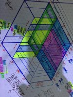
Oops I kind of forgotthe Important part.Anyone want to sim this ? It’s fine however you interpret it👍🏻I think I need your help..,i dunno what I’m trying to talk about anymore. 😂😂In pH mode you can see both sides of the driver and can put lengths and offset or normal path and it really exposes some unique things or opportunities. Typically something which appears to be perfection or whatever the word would be. Perfect alignment simple plain and easy but not easy to explain
The highlighted double-decker section trying to show them always exact same length passing through to the next segment along the way in order it is three dmsegments and one (in parallel) To the same endpoint
Attachments
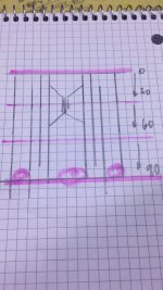
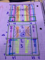
I'm not entirely sure how to view the schematics.It’s fine however you interpret it
In that most basic drawing with pencil and pink marker, I do not see any opening. I would think that there should be some aperture at the end of those slowly expanding horn segments. But if those pink round marks are some sort of port that means that you either intend to have three ports up to a different volume or just ending on one side of the enclosure.
"Perfect alignment"... Sounds like marketing to me. Or are you talking about symmetry?Perfect alignment simple plain and easy
At any rate, you say that the schematics are open to interpretation, do you have any specific driver in mind?
Edit:
The more I look at those drawings, the more I think bandpass. I doubt the expanding segments would make much of a difference in a bandpass enclosure, seeing as there seems to be a 200cm2(?) port about 120-140cm long at the end of it.
Last edited:
- Home
- Loudspeakers
- Subwoofers
- Hornresp