But current limit only doesn't protect output devices efficiently.
Typical device(*) might need limiting to 4A for an output short where 50V is across the device, but only 1A should the opposite output device fail shorted (100V case - secondary breakdown is a real inconvenience here as without a very stringent limit the failure will simply cascade to other device and vaporize something). Same output device could happily power resistive 4 ohm load peaking at 12A without a limiter.
So just a current limiter means either using 3 output devices for 12A, and having no protection against output-short-to-supply-rail, or using 12 output devices for 12A which is crazy.
The secondary breakdown is a tough thing to guard against without good VI slope response, and in practice this means highly reactive loads will risk the SOA even at very modest currents.
(*) example is NJW1302 in fact, although there only sees to be a 1 second line, not a DC line.
There's a whole question of what consitutes dynamic SOA when handling audio signals in class B, as typical conditions are intermittent and peaky rather than continuous, so arguably a good limiter handles dyamically changing load as intelligently as it handles voltage and current. In fact this might be an area for microcontroller intervention ideally, which can thermally model the device including secondary breakdown to inform an input limiter, as well as spot gross faults as fast as possible.
So long as its inside the feedback loop, fuse distortion is significant.
12A, even with a 4 ohm load is 288 Watts, which requires a minimum of 3 pair, if not 6 pair of bjt transistors just to handle the heat. For 8 Ohms, twice that. Even with modern 2n3055, +/-20V (40V rail-rail) and 2A are the limit. If you want a 4 Ohm capable amp, you need two pair even at +/-20V. Let me repeat, "Today, Silicon is cheap". Using ample parts is the only solution that doesn't backfire. Current limit creates a square SOA box that is stable. Just be sure the outputs can handle the limit current at the supply voltage. It gives precious milliseconds for fault detection to kick in. Reactive loads are a circular load line that do not fit in a VI SOA box.
Class-D fuses can be placed in the power supply, and the biggest problem with placing them in the output is using a good socket. But fault detection is a better idea.
Last edited:
The Maplin 2N3055H/MJ2955 disco amp had +/-45 volt rails and 225WRMS output using two pairs of output transistors. The 90 volts across the transistor at peak voltages should have blown them up due to breakdown voltage being reached, but didn't. My build lasted at least 5 years despite heavy use on the road.
12A, even with a 4 ohm load is 288 Watts, which requires a minimum of 3 pair, if not 6 pair of bjt transistors just to handle the heat. For 8 Ohms, twice that. Even with modern 2n3055, +/-20V (40V rail-rail) and 2A are the limit. If you want a 4 Ohm capable amp, you need two pair even at +/-20V.
I'm talking 12A full peak to the load, but the device is seeing much less power than the load for a full power signal - the worst case for each output device is about 150W peak power, and each device is only doing one half of the cycle, so its average dissipation is much less than this, perhaps 50W per device.
Just draw the load lines for 4 ohm resistor driven from +/-50V on the same graph as the datasheet SOA...
I am not talking about the practicalities of sizing an amp(*), I'm designing the VI limiter for that device at that supply voltage with a given max power (so far the package maximum is all I've worked with).
(*) reactive loads I've not considered other than to protect the output transistors from them.
Correcting the SOA curve for an actual heatsink - not considered this yet.
With +/-30 volt rails (using the spec max vceo) you need to dissipate 112.5 watts instantaneously driving a 2 ohm resistor. Half way up the rail the dissipated power peaks going down on either side. This is for a tiny fraction of a cycle, and for practical purposes the 10 millisecond SOA can be used. This could be handled by a single transistor, and certainly by two. Reactive loads are worse by a factor of two in practice, making the requirement 225 watts. If you are derating the devices to 80 watts you only need three. Why only double and not quadruple? Real speakers rarely go reactive by more than about 60 degrees. If they do there is something wrong with them. This requires half the peak current (7.5A) at the full rail voltage (30V). Any current drawn at more than the full rail voltage gets progressively shorter in duration and are not usually going to drive failures. Failures will usually come from relaxing SOA protection to allow this 60 degree condition without activating, and then attempting to drive a short. Which allows this condition to persist for entire half cycles at a time, not just the couple of milliseconds that it does when driving an elliptical load line. This results in not only the max instantaneous dissipation, but a high average power which heats the heatsink up much more than driving the speaker does. This is how Phase Linears blow out - the SOA is insufficient at Vce=75V. But it takes enough persistence at these conditions to heat it up before it does blow. Won’t go out with a cold heat sink - which is why they can do the scewdriver test in the lab and get away with it but subject it to mobile disco use and you take your life in your hands if you stand too close to it. Putting in MJ15024’s went a long way toward making them reliable but what really helped was a FAN and MJ15024’s.
I don't think we need to debate more about how many pairs we need to go for and how to place a protection locus.
This amp with 4 pairs can handle any "normal" load, even reactive, and still have enough SOA headroom, so the current locus chosen makes it transparent on a "normal" 8ohms resistive load.
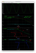
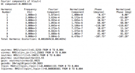
And on a reactive load, things don't get that much more scary, as seen on those attachments, I just ran it on 8ohms with 11uF in parallel, at about 215Wrms ouput, and it's doing just fine.
Things get a little less tidy when dropping the load to 4ohms, but I'm talking a 4ohms load on a bridge, so each side sees 2ohms, and even then, we're still not going over SOA. The chosen protection locus does make it start to act a little before reaching full power when the load is 4ohms, reactive or not, so it's not fully transparent then, but that's only a little before full power, so anything below that goes through just fine without limiter interference.
The only issue is when things get far more freaky, like a 2ohms load on the bridge, that's just 1ohms load for each side, nasty. And on a dead short on the output. Then at some frequencies, the limiter isn't acting quite hard enough to keep it 100% SOA safe. That's my main worry and I'm counting on having a sufficient input limiter to work in coordination with the vi limiter, which should keep it more within the SOA.
And if a dead short condition, or perhaps even an overly low load impedance could be detected as such, then an output SSR relay could be tripped, hoping the short to be beyond that and not inside the amp (very unlikely), so the relay tripping would remove the short and things are handled.
Now temperature sensors should also be on the heatsink(s), and be acted upon to keep things under control and prevent a disaster.
I have simulated a 5 pair version, and that may be the better way to go for those who want to bridge the bridge, even though 4pairs look like sufficient even for that.
One thing to keep in mind, is how many TO3s are to be heatsinked. With 4pairs, we have 8 TO3s per side, for 16 total to heatsink, so that's a fair amount of heatsink real estate.
With so many TO3s to cool, I think it's best to use 2 heatsinks, with 8 TO3s on each. At least one thermal sensor per sink should be used.
We can always go for even more silicon, with perhaps a 6pairs version, but that's getting pretty damn big and I'm not even sure a good heatsink large enough could be found.
This is the kind of heatsink I've had in mind for those amps:
Conrad Heatsinks - Products
Their largest one has enough room on the flange for 8 TO3s, so 2 of them looks like a workable solution. This can be "shaped" into a monoblock amp, with one large PCB with everything on it, to minimize external wiring and keeping things tidy.
This amp with 4 pairs can handle any "normal" load, even reactive, and still have enough SOA headroom, so the current locus chosen makes it transparent on a "normal" 8ohms resistive load.
And on a reactive load, things don't get that much more scary, as seen on those attachments, I just ran it on 8ohms with 11uF in parallel, at about 215Wrms ouput, and it's doing just fine.
Things get a little less tidy when dropping the load to 4ohms, but I'm talking a 4ohms load on a bridge, so each side sees 2ohms, and even then, we're still not going over SOA. The chosen protection locus does make it start to act a little before reaching full power when the load is 4ohms, reactive or not, so it's not fully transparent then, but that's only a little before full power, so anything below that goes through just fine without limiter interference.
The only issue is when things get far more freaky, like a 2ohms load on the bridge, that's just 1ohms load for each side, nasty. And on a dead short on the output. Then at some frequencies, the limiter isn't acting quite hard enough to keep it 100% SOA safe. That's my main worry and I'm counting on having a sufficient input limiter to work in coordination with the vi limiter, which should keep it more within the SOA.
And if a dead short condition, or perhaps even an overly low load impedance could be detected as such, then an output SSR relay could be tripped, hoping the short to be beyond that and not inside the amp (very unlikely), so the relay tripping would remove the short and things are handled.
Now temperature sensors should also be on the heatsink(s), and be acted upon to keep things under control and prevent a disaster.
I have simulated a 5 pair version, and that may be the better way to go for those who want to bridge the bridge, even though 4pairs look like sufficient even for that.
One thing to keep in mind, is how many TO3s are to be heatsinked. With 4pairs, we have 8 TO3s per side, for 16 total to heatsink, so that's a fair amount of heatsink real estate.
With so many TO3s to cool, I think it's best to use 2 heatsinks, with 8 TO3s on each. At least one thermal sensor per sink should be used.
We can always go for even more silicon, with perhaps a 6pairs version, but that's getting pretty damn big and I'm not even sure a good heatsink large enough could be found.
This is the kind of heatsink I've had in mind for those amps:
Conrad Heatsinks - Products
Their largest one has enough room on the flange for 8 TO3s, so 2 of them looks like a workable solution. This can be "shaped" into a monoblock amp, with one large PCB with everything on it, to minimize external wiring and keeping things tidy.
Attachments
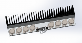
I dug out an older drawing that I made to check how much room there was on the conrad type of single flanged heatsink.
A couple of years back, I experimented with various heatsinking possibilities, for the grounded bridge and others.
This drawing shows how 8 TO3s can easily fit on that sink, along with drivers, pre-drivers and a bias sensor.
Now it might be a better idea to mount the bias sensor right on top of one of the TO3s, to speed up its sensing abilities. There is plenty of room for that much, so with 2 such sinks, the grounded bridge would be fine.
For maximum dissipation, it's probably best to use their largest model, and that's more than enough, with 2 of them, to fit everything, probably even for a 5pairs version of the bridge.
With thermal sensors on each sink, at the very least, there is no need for fans or whatever forced cooling.
Maybe a thermal sensing with 2 levels might be good, with action on a 1st level being only some input drive compression, and the highest level being the panic mode one, which would trip the output relay.
Attachments
I've been monopolized by other activities for some time and at my regrets, not having been able to spend time on the hobby, and I miss this very much.
This is still one of my main projects and eventually I will be able again to spend more time on it. It's fairly well advanced so far, and mostly ready for a prototype build. I guess that'll be the next step to tackle.
Actually I have more than one 3055 based build projects in the works, so plenty of work to continue working on..
") me too!!
me too!!Actually I'm still working on a big project that goes way back to the early 1980s.
Not giving any of them up, still in the pipes and coming. It just takes time.
Among the 3055 projects that are still on, there is the grounded bridge, one based on the excellent concept from John Ellis, one that can be made from this bryston based topology, and we worked collectively on one based on an old elektor based design which was a basic quasi at first and we made it into a complementary first and tried working towards a grounded bridge using the ideas from old Crown-Amcron.
Too bad this one based on the elektor idea never actually worked as a bridge in simulation. That amp works as a stand alone, but the grounded bridging would not work.
This would be great if the solution could be found to make it work properly.
Many are putting down the idea of making use of those trusty old and obsolete 3055s, but hey, that's what is interesting. Making those old parts do far more than they ever could before...
I've been taking about getting back on the hobby asap, but that will have to wait for now


Hi spooky
That bridge project certainly worked in simulation, but it needed a fully differential input.
That should not have been difficult to arrange, and yes, the output was fully differential too, so speaker output was +/- not +/ground.
Glad to see you are still persevering with this.
Many still say the 2N3055 is "no good" but the current epi version (has been since about 1988) has an ft of 2.5MHz and is certainly a lot better than the old RCA H device in terms of bandwidth which I suspect people are thinking of when 2N3055 is mentioned.
Particularly when Self criticised it as he used MJ802/4502 in his blameless, which are only 2MHz (but would have had higher gain at higher current. If I recall correctly he used MJE340/350 drivers which have lowish gain, so drivers like BD139 and BD140 would work well with 2N3055/MJ2955 - and do so in my now-getting-on-for 20 year old 50W amp).
Still, new designs will benefit from the new gen transistors, even though a respectable performance can still be had from 2N3055/MJ2955!
That bridge project certainly worked in simulation, but it needed a fully differential input.
That should not have been difficult to arrange, and yes, the output was fully differential too, so speaker output was +/- not +/ground.
I always favor fully balanced lines, so the fully diff input is a plus, a wanted feature. For those who don't have a diff signal, it's easy to add a diff line driver in front of it (like a drv134 or whatever), so it can be used no matter what.
Glad to see you are still persevering with this.
I am. I think it's a worthy design for a good project. It's a clever and excellent topology. I love it.
Many still say the 2N3055 is "no good" but the current epi version (has been since about 1988) has an ft of 2.5MHz and is certainly a lot better than the old RCA H device in terms of bandwidth which I suspect people are thinking of when 2N3055 is mentioned.
Sure. And for some, they can be substituted by those modern versions, the MJ15015/16, and boost the rails a bit more. Especially for those wary of pushing them beyond the 60V the 3055s are supposed to be limited by..
Still, new designs will benefit from the new gen transistors, even though a respectable performance can still be had from 2N3055/MJ2955!
Quite respectable for such old devices. And it's all more fun to push those to their limits, getting more out of them than ever.
Anyway, your design will hopefully get to be put into something real.
The 4 pairs with the 3055/2955 should provide quite a punch and satisfy very demanding applications.
I just wish I have free time to get back into this right now, but it'll have to wait some more. I'm too busy with non-hobby things for now.
@Boden
Yes, you are correct. Motorola offered the E version a long time ago. (And I think I got the date wrong. I'm now think RCA got the 2N3055 spec changed to the epi version in 1978, not '88.)
The latest ON semi device has a better SOA than the E now. Possibly because it may share the production line with another similar device (and I still measure breakdown voltages over 80V).
Though as TO-3 disappears the TIP3055/2955 pair are still worthy of consideration, now in TO-247 I think.
(and I still measure breakdown voltages over 80V).
What do you use to measure breakdown voltages?
Though as TO-3 disappears the TIP3055/2955 pair are still worthy of consideration, now in TO-247 I think.
I don't really like those plastic cases. Perhaps more practical for mounting purposes, but they have less SOA and the max temps is lower than with the metal cases. This means you need even more pairs to get the same SOA.
- Home
- Amplifiers
- Solid State
- Amplifier based on 2N3055