@sumilux
Here are 2 pdfs that summarise some of the detail.
some caveats:
- Peter Daniels found that leaving most of the stock caps actually sounded best for him
- I believe the cap labelled E6 on the pdf is where you want to spend your money >> can go as high as Duellund
- the mods on the laser unit are where you are going to get a big jump in SQ (see some recent posts of mine regarding recommended cap selections since this pdf was compiled)
- the trafo and psu from the boombox workfine until you get alternative >>> for trafo big was found to be better so go for 100va
- also many people found only supporting the transport mechanism at two diagonally opposite points rather then all 4 corners sounded better > when you hold the unit you can feel from the balance which of the 2 corners make best sense
be careful when removing parts - this pcb does not take much punishment
Attachments
Last edited:
I’ve been kind of busy trying to be responsible and get stuff done on the house and yard.
@sumilux. Thanks for the good words. I’m assuming that you may already have seen Peter’s other thread where he outlines his basic build process?
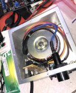
The CD Transport
I managed to work my way through building a Salas SSLV v1.1 to try as a power supply. It took me a while to get the current setting so it could handle the demands of the Shiga while reading the TOC.
By the time I got the SSLV set up properly I realized it was going to need a much bigger heatsink than was realistic. I wanted a compact supply design. It won’t go to waste as I can set it up to use with my D3 DAC project.
Afterwards, I managed to put together a supply similar to Peter’s original design that seems to work fine.
I found an LM7808 regulator equivalent made by NTE in a local shop which I put on some perf board with some Rubycon caps I had. I bipassed the first with a Silmic II and built the transformer and my own rectifier board from MUR860 into a small case I made.
I think it sounds better than the wallwort I was using previously. I might try the SSLV just to see if it makes any difference.
Other than that I did a little more trouble shooting and found that I had a clearance issue with my tray and the laser mech that was preventing it from playing the last tracks on long CDs. Took it back off and did a little machining on the underside. Now all is good. It plays very nicely.
I’ve only done Peter’s basic mods for now and am using my SMSL M8 while I gear up for my DAC project.
@sumilux. Thanks for the good words. I’m assuming that you may already have seen Peter’s other thread where he outlines his basic build process?
The CD Transport
I managed to work my way through building a Salas SSLV v1.1 to try as a power supply. It took me a while to get the current setting so it could handle the demands of the Shiga while reading the TOC.
By the time I got the SSLV set up properly I realized it was going to need a much bigger heatsink than was realistic. I wanted a compact supply design. It won’t go to waste as I can set it up to use with my D3 DAC project.
Afterwards, I managed to put together a supply similar to Peter’s original design that seems to work fine.
I found an LM7808 regulator equivalent made by NTE in a local shop which I put on some perf board with some Rubycon caps I had. I bipassed the first with a Silmic II and built the transformer and my own rectifier board from MUR860 into a small case I made.
I think it sounds better than the wallwort I was using previously. I might try the SSLV just to see if it makes any difference.
Other than that I did a little more trouble shooting and found that I had a clearance issue with my tray and the laser mech that was preventing it from playing the last tracks on long CDs. Took it back off and did a little machining on the underside. Now all is good. It plays very nicely.
I’ve only done Peter’s basic mods for now and am using my SMSL M8 while I gear up for my DAC project.
Attachments
@ sthcoaster...I’ve been searching for information relating to choosing different output resistor values in order to reduce the output voltage of my Shiga.
I can’t seem to find specifics.
I installed values as close to Peter’s recommendation of 100 and 300 Ohms at the ground pad and D Out respectively following the guide’s wiring instructions. The actual resistors I used were Vishay MK232 110 and 330 Ohm.
I am currently using an SMSL M8 as a DAC. There is no hardware gain adjustment. I thought perhaps the issue lay with the DAC, but once I set up the driver and Foobar2k on my laptop and tried streaming through it I had no issues with the gain level...even though it could be reduced via the software while streaming from the laptop.
I am using a Salas DCB1 based preamp which I’ve modified with Jensen transformers on the output for 6dB of gain.
When I play from the transport through the M8 the output level is so high that I can barely turn my pots up and have it already quite loud.
Normally, my pots are turned about 25-50% of their rotation which gives me normal to “enthusiastic” listening levels.
Any info you can point me at would be great.
Thanks in advance.
I've run the 100/300 combination with no problem but my system is generally low gain. Could be you just need to get closer to these values?
The original has 75r/75r
I've seen a combination that is around the values 90/390 (I can't remember the exact values)
Also some suggest using an RF attenuator can help with the spdif signal.
The original has 75r/75r
I've seen a combination that is around the values 90/390 (I can't remember the exact values)
Also some suggest using an RF attenuator can help with the spdif signal.
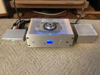
@sthcoaster and @chromenuts thanks ever so much for your informative replies and advice.
I’m going to approach this from a black shiga mkII angle first. @Tvicol has boards for sale so I’ll start there. All the laser mods will be done and The Mundorf oil cap makes sense. I’ll also be focussing on the cleanest over supply of linear power I can afford. May even go the route of an @iancanada UC supply or two though he only does 3.3 and 5v right now.
Taking much inspiration from your housing @chromenuts, please keep posting
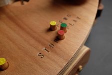
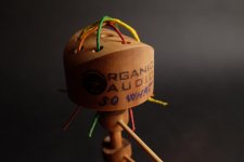
So what !
Attachments
-
 e2fe7729-89be-4cb6-9964-576ab2154e83.jpg42.6 KB · Views: 381
 -
 3154b446-984a-48cc-8398-f5aded51fee0.jpg51 KB · Views: 426
 -
 581a4f27-c3b1-4c3e-906d-d10512dbf163.jpg32 KB · Views: 367
 -
 58c85d91-6340-4769-aa0e-9216b32bd831.jpg44.1 KB · Views: 654
 -
 1cdde304-cd7f-401c-9cff-2ab23b20abef.jpg28.8 KB · Views: 665

So what !
I really like those "crazy" approaches! This is refreshingly different. Well done!!
So what !
Made my day seeing your crazy creation. Just love it.
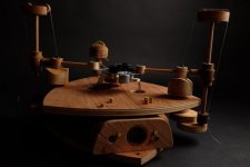
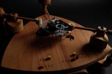
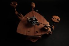
lohk ,I hope the prototyping period video is demonstrating at least the idea of the three planes of shock absorbing system.
Right now I am in the process of finishing the second sample of the same transport and I can take some pictures of the concrete solutions for triple planes for the two points absorption , as my work on it allows me...
Right now I am in the process of finishing the second sample of the same transport and I can take some pictures of the concrete solutions for triple planes for the two points absorption , as my work on it allows me...
Attachments
Last edited:
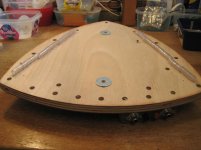
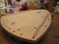
Electronic board which is coupled to the vibration of both first and a second platform , stands on the two discs which are part of the two wooden sticks , coupling the base platform and the upper one .
Everything is ''loose'' but firm at the same time ,no tight screwing ,no glue...
Everything is just laid down and the layers of the whole transport construction are hold together by two nylon threads which are also used to tune the vibration of the construction in the similar way that is done on an musical instrument.
Attachments
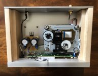
JVC RC-EZ31- need some help
I bought this boombox some years, did not get around doing anything but damaged the PS in the first week. Because I am a "half bucket" of water.
During this pandemic, really too boring, I need some new sparks. I took it out last night and fidled around a few hours. got it back to "work" again with 7.5v lithium camera battery pack and a external hard drive ps, the 12v extension, just for fun, but I have these problems hope some one can advise:
1. is that CN906 where i should send signals to a preamp? if Yes, Pin Assignment?
2. i found out from my copy, the speaker-out is from a connector CN301 (like that on EZ35), not CN332 per manual, confusing!
3. the manual circuitry is not borad by board, caused me some difficulty to read, afterall, i managed to find out those CN's. (i trashed all other things but the amp board and ps so no way to identify). except nowhere to find the EQ outs, i mean, treble, base and balance etc.... this boombox came w/o RM. can i make it work if i buy a universal one.
4. PS (a) i have had all IN4001 fried. I happen to have these in hand, replaced, but i still don't get the 8v. Is that becase 2SD2061 or the DZ401 8v zener trouble?
5. PS (b), i supplied 7.5vdc to 8v, nothing worked until i jumper it to 12v on CN303. same, nothing happened when i supplied 12vdc to 12v pin or DC+
6. PS (c), i ended up feeding 12vdc to CN1101 on PS board, the DC+ , then I got back 8v as well as 12v. i felt lucky not jumpering 12v to the 8v pins.
7. PS (d), still can't understand i did not get 8v from PS board with its built-in transformer, but ok with external 12vdc.
8. PS (e), can some some show me a simple PS circuit that i can get clean 12v and 8v, given to buy components is no longer easy these days.
i may have few more questions after, anyway,
thanks all for reading, have a happy day and stay safe!
Hi everybody!
I want to share some information that can help those who have a Sanyo DA11 transport with a laser head SF-P101 reads discs poorly.
This week I was repairing my Philips AZ1065 boombox, which first began to read discs with errors after just a year of operation and then completely stopped recognizing discs. Cleaning the lens didn't help, and cleaning and lubricating the mechanics didn't help either. I noticed that during the test described in the Philips AZ1065 service manual, the carriage motor cannot move it normally.
I began to check the condition of the motors. In the service manual of the Sanyo DA11 (SF-P101) drive, it is indicated that the motors should start rotating at a voltage of 0.8 volts or less. The disc motor started rotating at 0.6 volts, and the carriage motor only at 1.65 volts. Since the motors are the same, I measured the resistance of the motors with an ohmmeter. The disc motor had a resistance of about 12 оhms. The resistance of the carriage motor varied chaotically within a few hundred оhms.
I disassembled this motor. Its collector plates darkened to blue-black. I cleaned the collector plates with a rubber eraser and alcohol to a silvery color and reassembled the motor. Its resistance became 11.3 ohms in all rotor positions. After that, the drive began to perfectly read all discs - CD, CD-R and CD-RW.
In addition, I want to make some clarifications about the JVC RC-EZ51 boombox.
Very often in this thread it was mentioned that it is not suitable for Shiga, since it is made on the LC78690 chip instead of the LC78601 and LA9242. And they referred to the service manual (for example JVC RC-EZ55BB BE BEN BEV RC-EZ51HB HE HEN HEV RC-EZ53SE Service Manual download, schematics, eeprom, repair info for electronics experts)
But nobody pays attention that all the diagrams in this service manual are only for JVC RC-EZ55. This is written in the lower right corner of each diagram https://www.diyaudio.com/forums/attachment.php?attachmentid=943810&stc=1&d=1618780685
Apparently this service manual lacks pages with diagrams of RC-EZ51 and RC-EZ53 models.
Therefore, this service manual cannot be used for RC-EZ51. This is evidenced by the post of our colleague chromenuts Finally, an affordable CD Transport: the Shigaclone story
Sorry if something is not clear. I use Google translator.
Valery.
Last edited:
- Home
- Source & Line
- Digital Source
- Finally, an affordable CD Transport: the Shigaclone story