Ok. I hurried. I didn't take into account that your operational amplifier starts to reduce the gain. I used a perfect block and therefore my results are somewhat different, but this will not change the essence.I attached the opamp settings. I guess at 10khz it already starts to cut off in gain with such a Ccomp
value and that's what I "compensated" with this multiplier to get the same in/out amplitude.
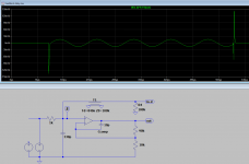
I repeated your scheme and will show how it looks for me (taking into account the fact that the amplifier block is perfect of course).
On the first slide we see the scaled input and output signals merged at the top - they are equal in amplitude. The lower graph shows the difference between them.
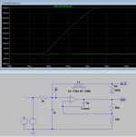
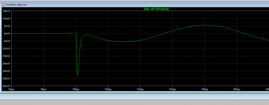
On the second slide, I compensated for the delay in the gain channel and did exactly the same subtraction. We get the difference between the input and output signals as it would look in the experience of Peter Baxandall. We see a spike at the beginning, and then everything becomes normal after the transition is over. The two lower graphs are the same, just a different scale. And there's nothing to worry about.


I responded to the comment about intention. Readers should beware when an opinion is forcibly presented as fact and simulation results are presented as measurement.So... a proponent of academic freedom ...
You still dont get it, I never said using unnatural signals in the math or sims was wrong, I said believing they actualy exist is wrong. Do you have a reading problem? And LTspice has a built in laplace function so more misinformation from you. LTspice can do "instant" (one time step) rise times if you want. And pretty sure microcap has a min time step that is the " speed limit".
Last edited:
Thanks for your simulation! And have you used some real life input LP filter?We see a spike at the beginning, and then everything becomes normal after the transition is over.
The two lower graphs are the same, just a different scale. And there's nothing to worry about.
BTW I guess there (could be) things to worry about as this happens on every new rising (transient starting) signal.
Therefore could you please show the "after life" section as well? What's the error there?
You still dont get it,
You said:
"Using a concept that doesnt exist in reality.."
I read that literally. It might have been more clear to say, "Using a concept that doesn't have an exact physical counterpart... "
The concept itself is valid and exits, it not something made up on the spot. In a similar vein someone might get attacked for saying a concept like noise floor modulation exists, since it is a term that some professional engineers think has clear meaning or they wouldn't use it. Someone else may argue that it "doesn't exist" as a valid concept because it isn't a "standard" term commonly taught to engineers in school.
However, I'm sorry for the confusion. People misread me sometimes too. As you do, I usually think what I am saying can't be read as meaning anything other than what I intend it to mean. Its a problem that happens in forums where meaning has to be taken from printed words, and there is no editor to check that everything is as well written as it might be.
With that, let the critics have their fun.
Last edited:
I usually think what I am saying can't be read as meaning anything other than what I intend it to mean.
What's that bias called?
")
A proponent is considered someone who publicly advocates something. Why would someone publicly advocate fake science?Like a proponent for anything, theres a point.
Better than a proponent for fake science.
Do you understand the topic or do you just want to argue against science?
Yes and no respectively. It comes down to a faulty interpretation of the spectrum generated from a continuous sinusoidal stimulus.
1st: that's the result if the delay is 840ns.Input filter: 1k + 330pF.Only if the transient was too fast.
2nd: that's the error with 430ns with 1k + 1nF filter.
3rd: just the error of the 430ns case.
And of course there's also a similar error at the end if the signal stops quickly.
Attachments
Maybe you never studied engineering math, specifically applications of the Laplace transform for electrical engineering calculations. The unit step function is an often used model since it can easily be transformed between the time domain and the complex frequency domain. In other words, concepts like step and or impulse models are used because of their mathematical convenience and their practical utility, not because they exist in physical reality.
Same thing for infinite duration sine waves when it comes to not existing in physical reality. Like I tried to explain before, we don't use idealized models because ideal devices, etc., exist in reality. We use them because they are very useful tools.
Regarding LT Spice, it obviously doesn't use Laplace transform engineering models or a step function would be supported.
EDIT: LT Spice does use other idealized models of components that don't exist in physical reality. Ideal controlled sources, etc. Those things don't seem to bother you.
Some fixes:
Laplace transform and Fourier transform are two different animals, physically and mathematically. There are some fundamental difference in properties:
- the result of a Laplace transform is a holomorphic complex fuction, therefore is analytic, meaning that it can be represented as a power series, which the Fourier transformation in general can not. See below the relationship between Fourier transform and Fourier series representations.
- The Fourier transform is equivalent only to a bilateral Laplace transform, meaning integration from -oo to +oo, up to a 1/2PI multiplicative constant, through the s->jw mapping.
- the Fourier theorem, the foundation of Fourier transform, makes no assumptions about the periodicity of the transformed function. In fact, the Fourier transform of the step function does exist and can be used for any analytical purposes. You could consider the Fourier transform of a periodic function multiplied by a time limited function (AKA "window") however the resulting Fourier coefficients will now be complex numbers, so you won't be able to use the common harmonic analysis of the result, in the frequency domain.
A non periodic function doesn't have a Fourier series representation. Only a Fourier series representation is "harmonic", meaning that the frequency domain components are integer multiples of the fundamental frequency. What we usually consider a "Fourier transform" is the Fourier series representation of a signal extension to periodicity.
LTSpice (or any other simulator) doesn't know a damn thing about Fourier and Laplace when solving the non linear set of equations. The Fourier analysis is a post processing step, in which the algorithm assumes the solver output as a periodic signal and calculates the Fourier coefficients of the Fourier series representation. So if you take the first cycle sine, the simulator makes this very signal periodic and calculates it's spectra. This has absolutely nothing to do with (electric, acoustic) reality since the result does NOT extrapolate the same way in the time domain as well. That's what our dear Russian troll refuses to digest.
Bottom line, if you want to do a harmonic analysis of a time limited signal you have to extend the signal to periodicity and calculate the Fourier series through the Fourier coefficients. Otherwise, the "harmonic analysis" concept makes no sense.
We are using the Laplace transform to calculate a system response in the time domain. One can view the Laplace transform as an alternative to solving differential equations (which is what a simulator effectively does). This has nothing to do with "harmonic analysis" and a Laplace analysis of the simulator output is useless, since we already have the results of the time stepping solving algorithm.
Last edited:
Ever read something like these?.... Why would someone publicly advocate fake science?...
"These devices work on the quantum mechanical level to eliminate sub-audible noise—i.e., noise unmeasurable by typical test-bench instruments. The results are previously unattainable resolution and beauty in home audio and video. For more than twenty years Original Equipment Manufacturers (OEM) and customers have used XXXXXXXX XXXXXXXX XXXXXXXX to enhance the performance of nearly every level of audio and video system." Which comes in a very beautiful package reasonably priced at only $$$$$$.
Surprisingly enough, sales of that particular product line has continued for decades now for a few hundred dollars a pop.
You wish to experience some false science? Fine, get the info at this place and go spend a few hundred $, your money, your choice. Just remember that the effect is both sub-audible and unmeasurable. You have been warned, have a nice day.Sounds amazing... where can I buy one?
syn08, kindly and tell me, have you made at least one amplifier in your life? If so, which one? What measurements did you take? What devices did you use?syn08
That's what our dear Russian troll refuses to digest.
If it's not difficult, share your work as Graham did, describing in detail the amplifier settings and the measurement results, and thereby leaving behind a good memory for those who understand this
There was an article about his amplifier on tubecad Upside-Down Differential Amplifier
Well, if you do not understand anything about development, but only a theoretician who is divorced from reality, then which of us is a troll?
Last edited:
.....
Bottom line, if you want to do a harmonic analysis of a time limited signal you have to extend the signal to periodicity and calcu....
Maybe you should stress here that this does not mean a static sine which some here would immediately think... just to be clear... - right?
//
- Home
- Amplifiers
- Solid State
- First cycle distortion - Graham, what is that?