It does resemble one of the Paraflex / Superplanar designs, but those are not positioned at TH alignments.
The TH I'm talking about is Art's Keystone.
Oh look at this guy !!

so close, but i think we are mass loading an offset orifice exit. i dont know if Brian built his yet(sundown?), but i can still put an aperture on mine at any point since the section is bolt on and sealed flanged already? i wonder....if this isnt just in the nick of time though... i can still model some things i can still implement in the design. its got the freedom of movement and a 12” stroke linear actuator mounted after the drivers in L34(Th1/Ap1)?
I model identical as an 18ds115 as 2 of my drivers are the just slightly damped less version of the same results always. Just 10-15% CSA shuffle is in the details...
Last edited:
Hi BP1Fanatic, Matthew (MMJ) did not do the ROAR, that is the nice work of Martinsson, Matthew did the super planar (sp8) the Planar tops and Paraflex subs, mids and tops.
Yes keystone sub, was my first thought even without Brian saying to move the output")
Im blind and never saw this beautiful device
The ROAR is a split path design with L12=0, so no, but good guess
Another hint - along with moving the mouth, change its shape
And if that doesn't help, make the cabinet a bit taller...
The ‘roar’ or paraflex can be split or not or partially. I think using each is how we can arrive at conclusions about flipping a port onto each side of the driver and realizing what offset driver really means. Offset port from
A driver as the source of that ports timing...etc, but It opens up the reasons an 8/10 order box is AMAZING for ‘science’ and interesting things to observe that might be a lot more than just ‘loud’ or ‘ efficient’. its possibly the greatest stone left unturned in the speaker game of stone mountains already climbed!
Folding and flipping impedance phase in a 4 quadrant approach surrounding a tapped driver at the 1/4 and 3/4 positions in segmented harmonic expansion points to keep the wave filtered and propagating is the potential FLH level of use and abuse without the idea of ‘zero impedance delta at the end of the 4/4 .
Its just a dog food duct in the corner. Theyve always been there, we dont look?
A tapped system is pointless once the halfwave mechanism lands on the driver acoustically at both ends.
A roar needs to be split in its initial path and given a MOAR in the middle if its second half twice as long using the FB in FW, not QW, and use all the tapped potential energy function thats based in HW. apply thus to the Freqs of that as its harmonics and the becon in the lighthouse is ignited. bring her to shore dont crash, its just Foggy... go slow. S is a fold shape. Its 4 quadrants of a sine wave with a driver at start and middle. now we use a sine wave to filter a sinewave. Or a 4 quadrant box folded around the idea its a ‘cycle’. and its harmonics are at dogfood ducts of the corksrew shape that is ‘tiers’ in CSA pipe segment advances.
I wish i knew a better driver but 18ds115(b/c) or 2 of my 12”Pflex drivers are tainted a bit in sim. They are nearly identical though. a 10% CSA reduction(qes of the ds115 motor) is enough to create the same results over and over. if the 18ds115 is ‘good’, then somebody look at the turd from china! Its $120 at holiday and $158 otherwise. SKAR ddx12d2 amazon free shipping
but red LE ? Its tricky.... so don't just buy it, look first. im apprehensive to make such bold claims alone. And it is so very very ‘stiff’ and breakin is 40 hours not 5?
Last edited:
If you have any questions about the spreadsheets, please post them to this thread, thanks!
The latest versions of the workbooks are available at this location:
The Subwoofer DIY Page
Brian
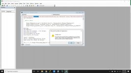
i have downloaded boxplan tl2 on dec 20th and tried it and get this error
im using office pro plus 2019 edition
win 10 pro version 64bit
Attachments
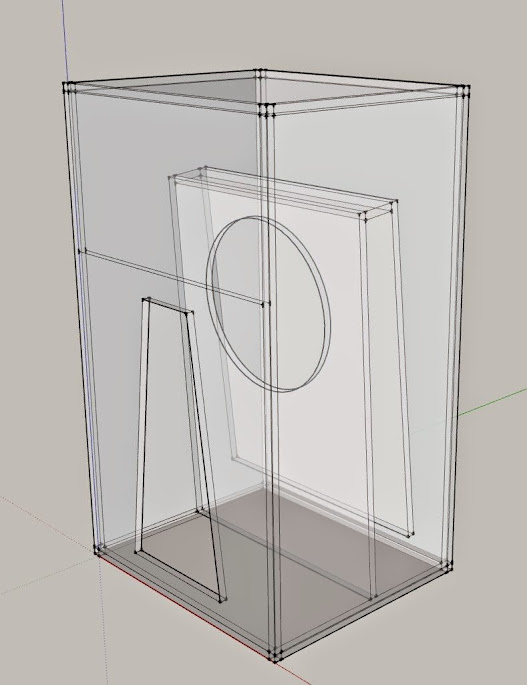
All of these excellent qw pipes with similar taped entry and qw lengths between them and an exit are exciting! And the doubler parafkex too.(pic)
this aperture sure adds an element i was previously just using a monster thumbnail round over bit on the 2x baffle thickness at various offset rectangular vent locations in a ‘Hroar type of design. . Bu it would be really fun to play with that shape instead, what a great sub, the ‘keystone’!
this aperture sure adds an element i was previously just using a monster thumbnail round over bit on the 2x baffle thickness at various offset rectangular vent locations in a ‘Hroar type of design. . Bu it would be really fun to play with that shape instead, what a great sub, the ‘keystone’!
Attachments
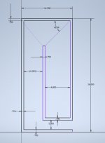
The concern that I have with that particular layout is that the insertion point of the rear vent into the front occurs at the open end of the front chamber, not at the closed end. This removes the extra loading that the front chamber can provide on the rear vent, so Fb isn't shifted down, as it would be if the insertion point happened at the closed end of the front chamber.
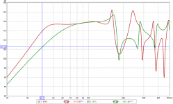
I've attached a graph showing a comparison between a 6BPS sim using the layout in my workbook, and the same thing with the front chamber removed. Fb shifts downward from 50 Hz to 40 Hz due to the front chamber. This allows the use of a shorter path for the rear chamber, which in turn means a smaller box requirement for a particular F3 point, all else being equal.
I've attached a graph showing a comparison between a 6BPS sim using the layout in my workbook, and the same thing with the front chamber removed. Fb shifts downward from 50 Hz to 40 Hz due to the front chamber. This allows the use of a shorter path for the rear chamber, which in turn means a smaller box requirement for a particular F3 point, all else being equal.
Attachments
Brian
i have downloaded boxplan tl2 on dec 20th and tried it and get this error
im using office pro plus 2019 edition
win 10 pro version 64bit
I've uploaded an updated version that's supposed to be compatible with both 32-bit Excel and 64-bit Excel. V0.2 BETA. Let me know how it works.
The concern that I have with that particular layout is that the insertion point of the rear vent into the front occurs at the open end of the front chamber, not at the closed end. This removes the extra loading that the front chamber can provide on the rear vent, so Fb isn't shifted down, as it would be if the insertion point happened at the closed end of the front chamber.
I always wondered about that situation. I thought the setup would act more like a BP6P than a BP6S.
Isnt this fun!???
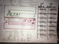
?Thats the null for the the 107 Hz 80cm HF pipe?. Sits right there if you think about it? 80 cm offset is a S4. Backwave to the source? its the HF chamber you found. But also, gold as in golden throat chamber for Vas another PITA!! Vas is the bomb
Try a CH version of Pfkex, its a fail. They fixed super planar by making Pflex. Thats why its so heavily tested before release. pretty cool.
Attachments
Last edited:
I always wondered about that situation. I thought the setup would act more like a BP6P than a BP6S.
I expect as much as well. And if that's the case, there really isn't any reason for that last bend in the rear chamber's path and it complicates the build a bit. Just bring it out at the bottom of the box instead. The low frequency response is likely not going to change that much, if at all.
In fact, I think I'll BOXPLAN a sheet for that to see what the results would look like ...
- Home
- Loudspeakers
- Subwoofers
- Spreadsheet for Folded Horn Layouts...