I cannot find the model for the 16N20.
But I want to make sure I understand the circuit properly.
So I simulated a preamp version that would drive 20k differential load.
Quite a lot of dependence between parts and certain limitations, as one would expect from such "simple" topology.
Thanks for sharing the idea,
Patrick
.
But I want to make sure I understand the circuit properly.
So I simulated a preamp version that would drive 20k differential load.
Quite a lot of dependence between parts and certain limitations, as one would expect from such "simple" topology.
Thanks for sharing the idea,
Patrick
.
Attachments
CCS loaded Zenitron


I have been exploring your CCS loaded Zenitron idea a bit.
I don't have any spice files for IXTH16N20D2, and I believe the UnitedSIC JFET UJ3N065080K3S is a better candidate for this application.
It seems to hit 12 watts output power at the onset of clipping. It clips very soft and gradual, much like a triode amp.
The two CCS could be made with IXTH16N20D2.

> I believe the UnitedSIC JFET UJ3N065080K3S is a better candidate for this application.
We agree on that certainly.
The Vgs limits your maximum output for a given gain.
No such issues in a follower.
> The two CCS could be made with IXTH16N20D2.
Suggest you look at IXTH20N50 if you do not need a lot of bias.
You can get the spice file at :
MOSFETs_Models
In order not to load the source, the feedback network wants to be something like 10K/100k (for gain of 10).
Not sure how that affects your bandwidth.
Otherwise quite elegant,
Patrick
Some thoughts perhaps on real-life implementations.
The power JFET is loaded by a CCS, and hence Vgs does not need perfect matching.
However, as bias is only determined by the two CCS’s, they have to be matched and stable at all times.
Any mismatch will readily manifest itself into a DC offset.
Those IXYS depletion MOSFETs have a significant positive tempco at bias.
So certainly not ideal for the job.
Here I propose two variants, using Renesas lateral MOSFETs (2SK1058).
These have a negative tempco at bias and are therefore self-stabilising.
One can also add an additional self-biasing circuit as shown on the RHS.
In that case the two NPNs for the current sources should be matched and thermally coupled.
For example, Toshiba HN1B01FU-GR.
Patrick
.
Attachments
Can you show a schematic drawing? I cannot make sense of the .asc file (I believe this is a SPICE file, and I have no clue about this).
Also, the 2K1058 is quite limited in terms of heat/power dissipation, and I am not sure if they are still in production.
What about the Exicon ECW20N20 laterals?
Datasheet: http://www.exicon.info/PDFs/ecw20n20.pdf
More detailed curves: USSA-5 Build with Review
Also, the 2K1058 is quite limited in terms of heat/power dissipation, and I am not sure if they are still in production.
What about the Exicon ECW20N20 laterals?
Datasheet: http://www.exicon.info/PDFs/ecw20n20.pdf
More detailed curves: USSA-5 Build with Review
Last edited:
Install LTSpice.
It is free, and useful for many things.
That will just open a new rabbit hole for me, and I already have too many. So I will stay away from LTSpice.
You are only dissipating 10~15W in the CCS.
2SK1058 is perfectly fine.
If you trust datasheets, then 2SK1058 has less early effect (more perfect penthode) than the exicons.
Oups! I thought you suggested to replace the United SICs with the Renesas because I was looking at United SIC datasheet and thought that these parts also have a rather strong positive tempco. Forget my comment.
I actually have a bunch of those SICs in a box somewhere...
So a quick attempt in Spice.
(You need to remove the ".txt" from the .cir filename and place in the same directory as the .asc files.)
Works OK, but rather poor efficiency, even compared to other P-P Class A.
And bandwidth limited to 20kHz -3dB; 10k load per phase to the source.
Right now, I rather prefer this one :
The New-Tron
But perhaps you can improve ?
Cheers,
Patrick
.
Attachments
Last edited:
But perhaps you can improve ?
Probably not. I would not build it with CCS. I prefer the simplicity and the sound character of large inductors over complexity, thermal drift and other problems associated with adding active devices.
The idea was to simplify the SoZ v7-T, as I already have the large transformer core inductors laying around unused.
The goal was to use the SoZ v7-T as a starting point, and without adding any complexity I wanted DC coupled inputs and outputs and fewer parts if possible.
The rock solid stability one gets from depletion mode devices working against a DCR set by the copper wire in a large inductor does work wonders for sound quality in my experience.
Even Nelson Pass alludes to the special sonic character of inductors in several of his articles.
Thanks for taking your time exploring the Zenitron layout. It is much appreciated!
Regards,
Johannes.
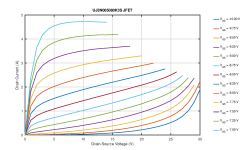
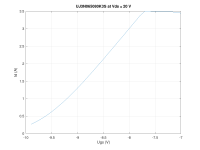
...and I believe the UnitedSIC JFET UJ3N065080K3S is a better candidate for this application.
I ran the UJ3N065080K3S through the curve tracer to see what the curves look like in reality, as the datasheet curves do not cover the typical "audio amplifier range" very well; see attachment. The flattening of the curves at high current is due to the self heating and negative tempco. However, I am not sure what's happening at 20 V and higher... is this normal for a JFET? What is it?
Attachments


I tried to simplify the power resistor current source, enhancement device, super symmetrical Zenitron as much as I could, and this is where I ended.
If one only needs a few watts output power, a fully balanced design, super symmetrical feedback, DC coupled in and output, and has a large stash of 24 volt switched power supplies laying around unused, then I guess this could be a fun design to fool around with.
Distortion drops substantially with higher voltage from the power supplies and more current through the devices.
I guess the UJ3N065080K3S would be best at 2A or higher.
This is very depended on how it is used but since this is the Pass Labs section of this forum I would argue that the sweet spot is around 15 volts drain to source and 0,5 to 1,2 ampere of current,
A nice smooth triody section of the curves - that is easy to "work the load line" for some distortion cancellation in simple one stage, low-to-non negative feedback single ended designs.
I tried to simplify the power resistor current source, enhancement device, super symmetrical Zenitron as much as I could, and this is where I ended.
This looks more interesting.
")
Would you care to share your spice file ?
Thanks,
Patrick
- Status
- This old topic is closed. If you want to reopen this topic, contact a moderator using the "Report Post" button.
- Home
- Amplifiers
- Pass Labs
- The Zenitron