Questioning about andrea_mori's results (2), Real SCK time jitter after FifoPi
OK, let's continue the testing.
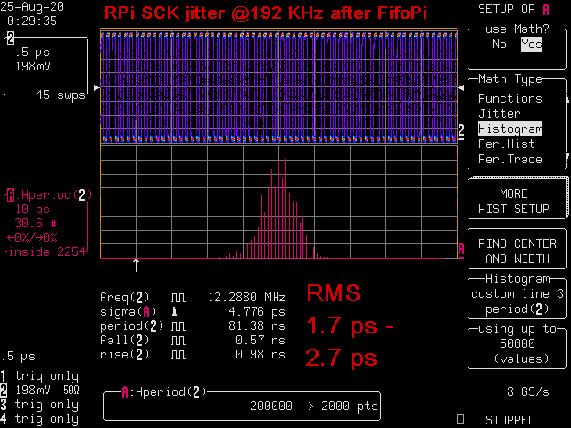
The first pictures is the time jitter histogram plot of the same RPi SCK but after FifoPi.
We can find all deterministic jitter has disappeared. Only some random jitter left. The random jitter has reduced to 2.7ps or bit less (with noise floor removed) from 247.8ps. All RPi SCK jitter was removed/isolated.
The FifoPi SCK jitter is now exactly the MCLK jitter + additive jitter of the flip-flop.
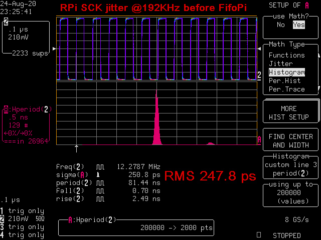
The second picture is the time jitter histogram plot of RPi SCK before FifoPi. Just for you to reference. You can see what a huge improvement that a FifoPi makes. All input RPi jitter was fully removed.
However, if it's based on andrea_mori's testing results, RPi SCK phase noise (the second picture) could be -7dBc better than the SCK after FifoPi phase noise (first picture). That doesn't make sense.
If his conclusions are all from his wrong testing results, I really can not agree with.
SCKafterFifoPi192 by Ian, on Flickr
SCK_RPi_192 by Ian, on Flickr
Regards,
Ian
OK, let's continue the testing.
The first pictures is the time jitter histogram plot of the same RPi SCK but after FifoPi.
We can find all deterministic jitter has disappeared. Only some random jitter left. The random jitter has reduced to 2.7ps or bit less (with noise floor removed) from 247.8ps. All RPi SCK jitter was removed/isolated.
The FifoPi SCK jitter is now exactly the MCLK jitter + additive jitter of the flip-flop.
The second picture is the time jitter histogram plot of RPi SCK before FifoPi. Just for you to reference. You can see what a huge improvement that a FifoPi makes. All input RPi jitter was fully removed.
However, if it's based on andrea_mori's testing results, RPi SCK phase noise (the second picture) could be -7dBc better than the SCK after FifoPi phase noise (first picture). That doesn't make sense.
If his conclusions are all from his wrong testing results, I really can not agree with.
SCKafterFifoPi192 by Ian, on Flickr
SCK_RPi_192 by Ian, on Flickr
Regards,
Ian
Last edited:
I don't see that the deterministic jitter is gone.
I see that it's location is now way out, 2 meters right of my screen.
And if you reduce the number of sweeps further from 45 to 1,
you have solved the jitter problem forever.
I also miss the bandwidth over which the RMS is taken and the
length of the uninterrupted time series in seconds. You won't capture
1/f effects in the 10 Hz range from 45 snippets each 100 usec long,
located at arbitrary intervals.
Gerhard
Last edited:
@gerhard, just a suggestion (please ignore if not right), maybe its worth telling Ian what he can and cannot measure with his setup, and how he should go about it. I think this may stretch out if left as is. Sorry if Im overstepping any boundaries by making the suggestion. Just think it would be good if we can keep the thread spirit positive. Your contributions are the governing element here, so can't request anyone else.
The crosstalk could be through the grounds or simple EMI. My first thought are from experience is the long ago times tuning the clock tree on the CDC6600. Back then we had trim caps to adjust the clock delays as they propagate through the CPU. In this case I would add a d type flip flop clocked on the back edge of the clock to resync the Mclock/Bclock/Wclock/data to as clean a clock as available. When trying to get clean timing ground noise become a significant issue and less than a millivolt of noise can seriously degrade the timing moving the transition reference point. This is a real limitation in FPGA's and other LSI. Most DAC chips have internal reclocking to deal with this but they are only as good at the clocks and power supplies coming in.
Since the firmware is unknown it's difficult to say where the crosstalk comes from.
I don't know if the PLL of the FPGA has been used to generate the output signals, if so the crosstalk could come from this.
It could be useful to capture the wave at the output of the FPGA cutting the rest of the circuit to better understand if the crosstalk comes from the FPGA or not.
And if not so it could be useful to see the waveform at the input and the output of the flip-flop to understand if the crosstalk is generated in the substrate of this IC.
Ground loop issue is another story and could be difficult to discover.
For sure the crosstalk shouldn't be there, the beating between frequencies will heavily modulate the phase noise of the signal, and consequently the jitter.
If I would like to convince Gerhard that I am not cheating and I am not only zooming in to the clean part of the cumulative jitter spectra..
I would use that same time window screen in persistence mode taken before, showing that 'outlier edges' are gone, there is only the main trace left, and at that moment one can zoom in.
But in the same time I don't see why should Ian hide behind such a simple trick. If he shows that only single jitter distribution, I would beleive that is the one only left.
On the other hand we can also ask, why is it that the spuries are supressed in Andrea's measurement, while those could show that the Fifopi is effectively removing some?
Heck. The unharmonic spuries are the most visible feature of badly organized units (dacs..)
Those are the ones even clearly visible in the dac's analog output spectrum.
Those are visible in Stereophile and ASR jitter tests.
On the contrary, only very refined testing (like Hans Peter of HPW does it) could reveal some little hint of the close in noise floor modulation, in a Dac's analog output signal... Just saying.
@Joseph
regardless of the spurs I wonder why the noise floor of the FifoPi LRCK is so high, almost the same of the RPI LRCK, while the noise floor of the MCLK is 20-30 dB better. Almost the same result with SCK.
I also wonder why FifoPi LRCK has crosstalk, crearly visible with the oscilloscope.
I also wonder why a cheap DDS signal generator has 20 dB better noise floor than the FifoPi.
Finally, I wonder why the FIFO buffer is source dependent, the better the clock of the source the better the sound.
I have my idea, but I'm here to learn, so please let me know.
If I would like to convince Gerhard that I am not cheating and I am not only zooming in to the clean part of the cumulative jitter spectra..
I was not commenting on anything from you, I was only commenting on #2462
and it is at least insufficient to support the claims.
And I don't want to be drawn into any feuds. Phase noise of crystal oscillators
in audio for me is about as interesting as watching flees copulate. Just imagine
the phase modulation in the output of a turntable when the center hole is 0.1mm
off. The entire spectrum moves up/down twice per revolution.
Or a capstan that is not really round.
I care about the phase noise of the reference oscillator that drives the 10 GHz
synthesizer on my table. If you multiply enough upwards, THAT is a show stopper.
BTW
There is an interesting article by Rohde, Poddar, Apte in IEEE microwave magazine
sept/oct 2013: How Low Can They Go? It's behind the IEEE paywall, but I must
have found it in the wilderness of the net ;-) and a lot of similar from the same bunch
of authors. They discuss the pros and cons of many methods of phase noise
measurements. There is not a single mention of using a scope and some jitter
software, that clearly does not make the top ten.
Last edited:
Driscoll phase noise measurements
The phase noise plots of the Driscoll oscillator with a new set of crystals at all the frequencies.
The phase noise plots of the Driscoll oscillator with a new set of crystals at all the frequencies.
Attachments
The phase noise plots of the Driscoll oscillator with a new set of crystals at all the frequencies.
Looks good Andrea!
A couple of questions out of sincere interest...
1) How does the 5.6 MHz w. 2x frequency doublers compare to the 22.6 MHz?
2) Possibly a (very) stupid question. When comparing oscillators with different frequency is it 'better' to compare the phase noise at 'equal' or 'equal relative' distance from the carrier (i.e. @ 10 Hz for both 5.6 and 22.6, or 10 Hz for 5.5 and 40 Hz for 22.6)?
Just curios.
Keep up the good work!
Ian,
I have access to a Timepod and I also have a full HP3048 / E550X Agilent phase noise system in the lab, and the Timepod gives these high end systems a run for there money and is certainly quicker and easier to use!
I've been watching this thread with interest as I've spent many years designing LPN clock circuits.
I've seen little wrong with Andrea's developments / measurements although he can sometimes have an abrasive writing style... but I'm more inclined to believe that maybe just something is being lost in translation as English is not his mother tongue.
I would trust in his Timepod measurements over a digital sampling scope with a Jitter measurement package - ESPECIALLY when we are talking about close in carrier measurements (LF Jitter measurements)...
Digital scopes are not designed for high dynamic range nor LF noise performance - the reference timebase on an oscilloscope will not be temperature compensated and will sway about like a drunken sailor when compared to the Oven compensated oscillator used as the Timepods reference.
The argument seem to be based on you FifoPi LRCK output, this can be measured directly with an decent Audio FFT anayser - todays anaylyers will have an FFT noise floor of around -160dB which is plenty good enough to directly see any Phase noise issue.
Is there a schematic of your FifoPi? if the LRCK is outputted from an FPGA / CPLD then this will be the cause of the higher PN.
I'd be happy to make independent measurements of your FifoPi, as I say I have a Timepod, full HP3048 / Agilent E550X & Wavecreast phase noise systems.
Andrea,With the 5.645 MHZ the battery has the advantage at 10 Hz, on the rest of the spectrum the difference is not huge.
The new Driscoll oscillator is not much sensitive to the power supply so a good linear regulator does the job almost like batteries, although I would decouple it from the main AC.
BTW, the battery power supply has been designed not only for the oscillators but for the whole digital chain, except for the FIFO buffer because it operates in a differente domain and is optically isolated.
We plan to power with battery the sine to square converter, the dividers and the DAC in both Lite and top version.
Last edited:
Looks good Andrea!
A couple of questions out of sincere interest...
1) How does the 5.6 MHz w. 2x frequency doublers compare to the 22.6 MHz?
2) Possibly a (very) stupid question. When comparing oscillators with different frequency is it 'better' to compare the phase noise at 'equal' or 'equal relative' distance from the carrier (i.e. @ 10 Hz for both 5.6 and 22.6, or 10 Hz for 5.5 and 40 Hz for 22.6)?
Just curios.
Keep up the good work!
We are still working on the frequency doubler, so you have to wait for a comparison between 22/24 MHz and 5/6 MHz followed by frequency multiplier.
About the comparison between oscillators at different frequency keep in mind that every time you double the frequency the phase noise increases and the progression is not linear.
As I said several times the best phase noise performance is reached with crystals at a frequency around 5 MHz, so I suggest to use the lower frequency your system requires.
Questioning about andrea_mori's testing(3), Real RPi LRCK time jitter measurement
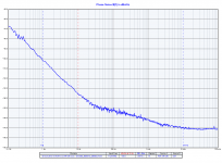
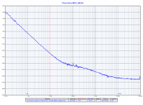
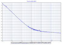
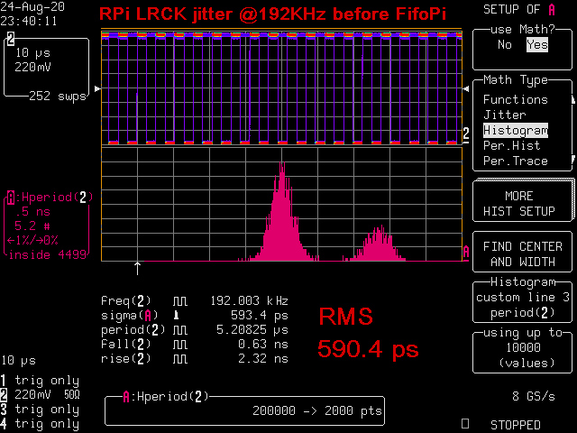
The first picture is the time jitter histogram plot of my RPi 4B LRCK signal before FifoPi. I2S was running at 192KHz 32bit.
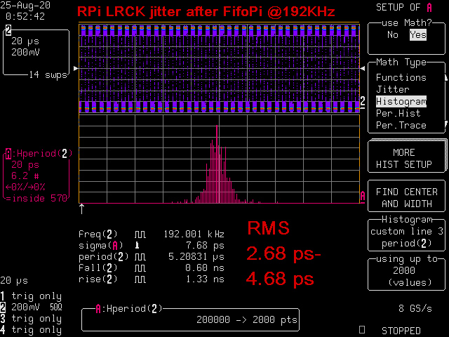
The second picture is the time jitter histogram plot of the same LRCK signal after FifoPi.
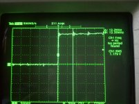
The third picture is the direct analog waveform view of RPi LRCK before FifoPi.
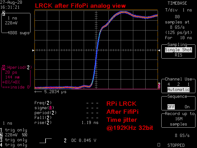
The fourth picture is the direct analog waveform view of the same RPi LRCK after FifoPi.
Testing results:
1. RPi LRCK signal has both random jitter and deterministic jitter. The two deterministic jitter deltas separated in around 1.3ns in between, both of them are very strong. which were from the systematic jitter of RPi internal PLL (to generate audio clock). The overall RMS jitter measured was 590.4ps .
2. After FifoPi, all deterministic jitter was removed. Based on the principle the LRCK jitter will be exactly the MCLK jitter + additive jitter of flip-flop. However, the jitter measurement noise floor seems to be a bit bigger because the sampling length was 64 times longer than the SCK. The LRCK time jitter after FifoPi is around 2.68 ps to 4.68 ps if excluding the noise floor. I think that's pretty reasonable. All input RPi LRCK jitter was removed. Output LRCK jitter has no business with LRCK input (jitter isolation).
3. Observation directly from the analog waveform also clearly supports the above testing results.
4. Rising time also reduced to 1.19ns from 2.25ns because FifoPi output has much higher bandwidth and speed.
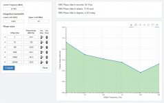
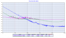
I attached andrea_mori's LRCK phase noise plot and phase jitter calculation for reference. I see three problems in his testing results.
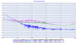
1. His phase noise plot (pink) didn't show any RPi LRCK systematic jitter signature in frequency domain (the pink curve). What was missing?
2. His FifoPi LRCK phase jitter calculated was RMS 66.19ps, roughly 20 times higher than the 2.68 ps to 4.68 ps time jitter measurement result. That's totally wrong. I don't think his measurement and calculation are reliable.
3. In his measured phase noise plot, the LRCK signal before FifoPi (pink) and after FifoPi (green) look almost the same. That's very unreasonable. The huge difference can even be clearly figured out from the analog waveforms, why can not his TimePod see it? Can we trust his 192KHz out of input range testing results?
LRCK_RPi_192 by Ian, on Flickr
LRCKafterFifoPi192 by Ian, on Flickr

LRCK_RPi_192_Direct by Ian, on Flickr
LRCKafterFifoPi192_Analog by Ian, on Flickr
-----------------------------------------------------------------------------------
My testing condition:LeCroy LC584 AXL real time high speed digital scope with jitter package running at 8GS/s
1GHz fully bandwidth without any filtering/limitation
Jitter measurement profile: period jitter histogram with RMS jitter calculation
real time jitter observation: Trigger at first raising edge, watch the following raising edge (cycle to cycle jitter)
Jitter noise floor (2ps to 3ps), could be even a bit higher for longer sampling length.
Regards,Ian
@Joseph
regardless of the spurs I wonder why the noise floor of the FifoPi LRCK is so high, almost the same of the RPI LRCK, while the noise floor of the MCLK is 20-30 dB better. Almost the same result with SCK.
I also wonder why FifoPi LRCK has crosstalk, crearly visible with the oscilloscope.
I also wonder why a cheap DDS signal generator has 20 dB better noise floor than the FifoPi.
Finally, I wonder why the FIFO buffer is source dependent, the better the clock of the source the better the sound.
I have my idea, but I'm here to learn, so please let me know.
The first picture is the time jitter histogram plot of my RPi 4B LRCK signal before FifoPi. I2S was running at 192KHz 32bit.
The second picture is the time jitter histogram plot of the same LRCK signal after FifoPi.
The third picture is the direct analog waveform view of RPi LRCK before FifoPi.
The fourth picture is the direct analog waveform view of the same RPi LRCK after FifoPi.
Testing results:
1. RPi LRCK signal has both random jitter and deterministic jitter. The two deterministic jitter deltas separated in around 1.3ns in between, both of them are very strong. which were from the systematic jitter of RPi internal PLL (to generate audio clock). The overall RMS jitter measured was 590.4ps .
2. After FifoPi, all deterministic jitter was removed. Based on the principle the LRCK jitter will be exactly the MCLK jitter + additive jitter of flip-flop. However, the jitter measurement noise floor seems to be a bit bigger because the sampling length was 64 times longer than the SCK. The LRCK time jitter after FifoPi is around 2.68 ps to 4.68 ps if excluding the noise floor. I think that's pretty reasonable. All input RPi LRCK jitter was removed. Output LRCK jitter has no business with LRCK input (jitter isolation).
3. Observation directly from the analog waveform also clearly supports the above testing results.
4. Rising time also reduced to 1.19ns from 2.25ns because FifoPi output has much higher bandwidth and speed.
I attached andrea_mori's LRCK phase noise plot and phase jitter calculation for reference. I see three problems in his testing results.
1. His phase noise plot (pink) didn't show any RPi LRCK systematic jitter signature in frequency domain (the pink curve). What was missing?
2. His FifoPi LRCK phase jitter calculated was RMS 66.19ps, roughly 20 times higher than the 2.68 ps to 4.68 ps time jitter measurement result. That's totally wrong. I don't think his measurement and calculation are reliable.
3. In his measured phase noise plot, the LRCK signal before FifoPi (pink) and after FifoPi (green) look almost the same. That's very unreasonable. The huge difference can even be clearly figured out from the analog waveforms, why can not his TimePod see it? Can we trust his 192KHz out of input range testing results?
LRCK_RPi_192 by Ian, on Flickr
LRCKafterFifoPi192 by Ian, on Flickr
LRCK_RPi_192_Direct by Ian, on Flickr
LRCKafterFifoPi192_Analog by Ian, on Flickr
-----------------------------------------------------------------------------------
My testing condition:LeCroy LC584 AXL real time high speed digital scope with jitter package running at 8GS/s
1GHz fully bandwidth without any filtering/limitation
Jitter measurement profile: period jitter histogram with RMS jitter calculation
real time jitter observation: Trigger at first raising edge, watch the following raising edge (cycle to cycle jitter)
Jitter noise floor (2ps to 3ps), could be even a bit higher for longer sampling length.
Regards,Ian
Attachments
Last edited:
"The LRCK time jitter after FifoPi is around 2.68 ps to 4.68 ps if excluding the noise floor."
"His FifoPi LRCK phase jitter calculated was RMS 66.19ps, roughly 20 times higher than the 2.68 ps to 4.68 ps time jitter measurement result. That's totally wrong. I don't think his measurement and calculation are reliable."
Well, let remove the noise floor from the integration bandwidth and magically the calculated jitter from the phase noise plot become 6.3 ps as in the second picture.
If you like then remove the noise floor so the calculated jitter matches your measurement.
But the noise floor is here, the first picture shows the amount of each integrated segment, 60 ps of the total jitter come from the noise floor.
Again, you look at jitter while I trust the phase noise, I don't want convince you, but try to read carefully the posts from other members, they have explained better than me what you have to look for.
"Observation directly from the analog waveform also clearly supports the above testing results."
And also clearly shows a crosstalk, confirming the captured waveform of the third picture already published.
"The huge difference can even be clearly figured out from the analog waveforms, why can not his TimePod see it? Can we trust his 192KHz out of input range testing results?"
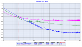
You forgot that you have the same noise floor issue with the SCK.
Please, take a look at the 4th and 5th plots, the noise floor of the SCK is even worse than the noise floor of the LRCK.
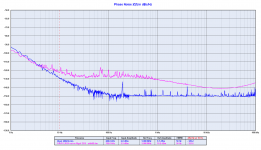
Moreover, if you don't trust the LRCK phase noise absolute values, take a look at the 6th, it's a comparison, so you can read it as a relative measurement: the noise floor of the FifoPi LRCK is 20 to 30 dB worse than a DDS signal generator.
It looks like you have noise floor issue, at all outputs and frequencies.
Again, please read carefully some posts from other members, they have suggested where the noise floor issue might arise.
P.S.
I have an Allo Kali somewhere, I will measure it as soon as I find the time, so we can do a comparison.
"His FifoPi LRCK phase jitter calculated was RMS 66.19ps, roughly 20 times higher than the 2.68 ps to 4.68 ps time jitter measurement result. That's totally wrong. I don't think his measurement and calculation are reliable."
Well, let remove the noise floor from the integration bandwidth and magically the calculated jitter from the phase noise plot become 6.3 ps as in the second picture.
If you like then remove the noise floor so the calculated jitter matches your measurement.
But the noise floor is here, the first picture shows the amount of each integrated segment, 60 ps of the total jitter come from the noise floor.
Again, you look at jitter while I trust the phase noise, I don't want convince you, but try to read carefully the posts from other members, they have explained better than me what you have to look for.
"Observation directly from the analog waveform also clearly supports the above testing results."
And also clearly shows a crosstalk, confirming the captured waveform of the third picture already published.
"The huge difference can even be clearly figured out from the analog waveforms, why can not his TimePod see it? Can we trust his 192KHz out of input range testing results?"
You forgot that you have the same noise floor issue with the SCK.
Please, take a look at the 4th and 5th plots, the noise floor of the SCK is even worse than the noise floor of the LRCK.
Moreover, if you don't trust the LRCK phase noise absolute values, take a look at the 6th, it's a comparison, so you can read it as a relative measurement: the noise floor of the FifoPi LRCK is 20 to 30 dB worse than a DDS signal generator.
It looks like you have noise floor issue, at all outputs and frequencies.
Again, please read carefully some posts from other members, they have suggested where the noise floor issue might arise.
P.S.
I have an Allo Kali somewhere, I will measure it as soon as I find the time, so we can do a comparison.
Attachments
-
 FifoPi_LRCK_Calculated_RMS_JITTER.jpg162.3 KB · Views: 160
 -
 FifoPi_LRCK_Calculated_RMS_JITTER_without_noise_floor.jpg158.4 KB · Views: 171
 -
 09 fifopi_lrck-jpg.jpg136.9 KB · Views: 165
 -
 03 rpi-fifopi-lrck-crystek-cchd-957-24-576-mhz-phase-noise-png.png102.8 KB · Views: 166
 -
 02 rpi-fifopi-sck-crystek-cchd-957-24-576-mhz-phase-noise-png.png106.5 KB · Views: 158
 -
 Rigol DDS vs FifoPi LRCK.png79.2 KB · Views: 139
Last edited:
I would trust in his Timepod measurements over a digital sampling scope with a Jitter measurement package - ESPECIALLY when we are talking about close in carrier measurements (LF Jitter measurements)...
Digital scopes are not designed for high dynamic range nor LF noise performance - the reference timebase on an oscilloscope will not be temperature compensated and will sway about like a drunken sailor when compared to the Oven compensated oscillator used as the Timepods reference.
I have said the same several times, I would add that in digital audio we are looking for the best phase noise close in to the carrier and a digital oscilloscope cannot measure accurately in this region, as you said the timebase is not suitable.
Is there a schematic of your FifoPi? if the LRCK is outputted from an FPGA / CPLD then this will be the cause of the higher PN.
No schematic and firmware is unknown, but I suspect the same, I'm almost sure that SCK and LRCK are generated inside the FPGA, I don't know if the PLL was used to generate the signals.
The crosstalk indicates that there is an interference with the SCK.
I'd be happy to make independent measurements of your FifoPi, as I say I have a Timepod, full HP3048 / Agilent E550X & Wavecreast phase noise systems.
Your measurements are welcome, I look forward.
Andrea,
The crosstalk is probably due to FIFO_Pi, IIRC, clocking out BCLK, LRCK, and DATA through one Quad Flip-Flop chip. Thus, there can be common ground bounce and other effects that could couple some crosstalk. (Don't have board in front of me right now, but its easy enough to read part numbers on the chips and trace out where clock lines go. Did that some time ago.)
On the other hand, again IIRC, MCLK is buffered out by a NB3L553-D, which powered from the same voltage regulator as used for the clocks themselves.
- Status
- Not open for further replies.
- Home
- Source & Line
- Digital Line Level
- The Well Tempered Master Clock - Building a low phase noise/jitter crystal oscillator