It wouldnt be very effective when the actual load points are all the OPA power pins and the traces from board power input to the OPAs likely adding as much impedance as the wires from reg.
You pick the device which is believed to be most susceptible -- it makes a difference for the Borbely "All FET" preamp with poor PSRR, other discrete designs, probably not as effective with an op-amp design with high PSRR.
Also I think I read earlier the sense line RC filter to is to ensure stability with long sense lines but is reducing bandwidth of the reg, with the sense line not in use could I possibly remove the filter and increase the bandwidth?
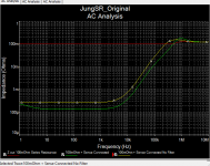
Assume for a moment that you have 100 milliOhms of "resistance" in between the SR and the DUT. If you don't use the Sense terminals you've taken a high performance engine and turned it into a two-banger. This illustration was done using the AD825 error amplifier. With the AD797 Z out will be a couple microOhms! (But "simulated" phase margin @1.3MHz is inadequate with the AD797).
Attachments
Last edited:
So I just took delivery of a pair of super regulator boards and I have a question.
There is a pad underneath the opamp connected to pin 2. What is this pad for?
I've been bracing myself for the new (to me) task of soldering the AD825 directly to the board (I assume this is optimal or else why provide the SMD pads, right?) If I have to make a connection to that pad under the device do I do that before soldering the AD825?
Or is it a better choice to use sockets and adapters either way? Or choose the AD817?
(I assume this is optimal or else why provide the SMD pads, right?)
No. The DIL & SMD combo is there to give you a choice. Some opamps are no longer available in DIP.
Jan
... is reducing bandwidth of the reg, with the sense line not in use could I possibly remove the filter and increase the bandwidth?
Reducing the bandwidth? Did you do the sums for 100 ohms and 100pF ??
Jan
There is a pad underneath the opamp connected to pin 2.
What does it connect? There's another one close by. It's called a via.
Jan
Last edited:
Yes. A via is used to continue a trace on another layer if there's another track in the way. The via you mentioned connects the DIL pin2 with the SMD pin 2.
You normally try to minimize the number of vias, but it's a trade-off between a via or a very long roundabout track.
Look at a PC motherboard if you get a chance. There's literally 100's of them, maybe even 1000's.
And then there's blind vias, which connect an outer PCB layer to an inside layer, or two inside layers.
Jan
I am not a trained EE or tech.
I have a question regarding op amp use in RIAA circuits. I see some circuit designs take a simplistic route and use an RC circuit to power the op amps to reduce ripple and noise. In so doing, it raises the source impedance to the power pins on the op amps. On the other hand some circuits use a Super Reg to power these same op amps power pins with requisite decoupling.
Any comments on what is the better way to go about this. Should one bypass the RC feed and power the op amps directly or should one feed the RC supply with a Super Reg?
Anyone care to clarify which is better?
It's not that easy, I'm afraid. You'll need base current for this pass transistor.Can someone explain why a higher current version, using just a higher wattage pass transistor, wouldn't it be feasible?
At the Chinese PCB fab where I buy a lot of my boards, the extra charge they apply for "2 ounce copper" is approximately the same as the extra charge they apply for "4 layer PCB". So when designing a new Super Regulator PCB to handle, let's just say, 3 amperes of output current, there are now more choices.
For those of us in the US, and for smaller boards, Osh Park does 2 Oz copper for the same $5 per square inch as their base boards. It just takes them a week longer to fit into a 2 Oz panel. That can come in handy.
Last edited:
Probably a stupid and already answered question.
I was reading again setting the right parts for the output voltage you will be using on your super-regulator.
Mine will be 30v, so if I follow the instructions, first thing is to adjust D2 and D7 zener to 15v, which would put me in the middle of my 30v.
But what about D5 and D10? Should I put a 15v zener there too?
The instructions tell you what to do if your output voltage is lower, changing D5/D10 to LM4040-2.5. But say nothing if the output voltage is higher.
As the important thing is the noise of that reference, I wonder which would be the right part for 30v output.
Any hints on how to re-calculate those resistors? Any formula?
On my sim I had kept all the resistors as on the booklet schematic, that is 1K for R6, R7, 4K99 for R5 and 499 for R4. Changed D2 to 15v zener.
But for that I did change D5 to a low noise 15v zener: BXZ384B15. The sim worked fine... but it's a sim.
On my sim I had kept all the resistors as on the booklet schematic, that is 1K for R6, R7, 4K99 for R5 and 499 for R4. Changed D2 to 15v zener.
But for that I did change D5 to a low noise 15v zener: BXZ384B15. The sim worked fine... but it's a sim.
The +inp of the opamp is at the ref voltage.
You have two resistors in series, the midpoint also has to be at the ref voltage (opamp +inp and -inp need to be at the same voltage).
The top of the two resistors in series is at 30V.
Can you calculate the top resistor if the bottom one is 1k?
Jan
You have two resistors in series, the midpoint also has to be at the ref voltage (opamp +inp and -inp need to be at the same voltage).
The top of the two resistors in series is at 30V.
Can you calculate the top resistor if the bottom one is 1k?
Jan
The +inp of the opamp is at the ref voltage.
You have two resistors in series, the midpoint also has to be at the ref voltage (opamp +inp and -inp need to be at the same voltage).
The top of the two resistors in series is at 30V.
Can you calculate the top resistor if the bottom one is 1k?
Both +inp and -input are at exactly the same voltage on my setup (14.988v), using 15v Zener as reference voltage.
You ask me just the question I did ask. How to compute the resistors if using LM329.
Both +inp and -input are at exactly the same voltage on my setup (14.988v), using 15v Zener as reference voltage.
You ask me just the question I did ask. How to compute the resistors if using LM329.
Please read my post. Do you understand what I am trying to say? Pencil in the voltages in the schematic. If you use a 6.9V ref, the bottom 1k resistor obviously has 6.9V across it. What is then the voltage across the top resistor?
Jan
Please read my post. Do you understand what I am trying to say?
Maybe not
...How to compute the resistors...
Google 'non inverting op-amp gain equation', that will answer your question.
- Home
- The diyAudio Store
- Super Regulator