Here is a guy who DIYed a servo linear
[/url]
Do we know if he continued and resolved the problems identified?
I know with my LTA when the carriage is raised and moved back to park it is audible through the speakers.
[/url]
Is that the mechanical noise being picked up by the cartridge during that motion please?
It's a working system albeit eye warteringly expensive
Dereneville
Yes on my LTA it is the cartridge picking up the wheels traveling on the rail. If you move the carriage slowly is it inaudible. I guess the point is making a servo control quiet will be a challenge.
Dereneville
Yes on my LTA it is the cartridge picking up the wheels traveling on the rail. If you move the carriage slowly is it inaudible. I guess the point is making a servo control quiet will be a challenge.
Yes on my LTA it is the cartridge picking up the wheels traveling on the rail. If you move the carriage slowly is it inaudible. I guess the point is making a servo control quiet will be a challenge.
For me, if i eventually take the plunge to build something i would want to build something that is noticeably better than what i have and is simple enough that i can build it.
Although i have surprised myself recently building and programming speakers with a DSP ( with lots of outsider input and coaching on this site) i cannot feel its at all likely i will build a servo driven arm and therefore the passive system seems more likely and simple and mechanical enough to cope with even if the servo route might be superior.
So, several people have said their experience with Passive LTA have exceeded any pivot arm they've heard, including the best around, if i take that as read, which way to go?
As a new joiner its quite hard to assimilate the enormous amount that's been posted here and elsewhere, so it may take a while to know what's there, let alone understand it all!
I definitely don't want to embark on a route that might fail, so might prefer small variations on a proven route.
I also took a couple of searches on line and its amazing how much is out there, not sure if that helps or hinders!
Yes on my LTA it is the cartridge picking up the wheels traveling on the rail. If you move the carriage slowly is it inaudible. I guess the point is making a servo control quiet will be a challenge.
Were you kind enough to post drawings and pics of yours? - if so could you kindly guide me to the latest,
also Niffy and others if you would, i can feel the possibility of taking benefit from your ideas, sourcing manufacturing ideas etc and perhaps being able to get off the ground later in the year........
i like to get comfortable with one bit at a time, I remember assembling the first clutch (car) i did about 45 years ago and being astounded that it worked, and feel to be in the same place here!
Is a servo arm superior???? I guess that depends. The Dereneville I linked to the guy who developed it said the development cost was the price of a house in Germany. One of the challenges to overcome was servo motor noise into the audio signal. I also see this as the biggest hurdle to overcome in a DIY servo arm. Servos are easier now as you could buy the parts on eBay.
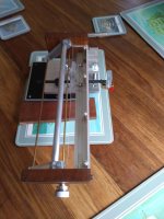
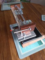
My first LTA was a simple affair, and quite easy to build. This simple arm bettered my Technics EPA100 in bass reproduction with the same cartridge mounted. I was surprised how good an arm made of basically scrap could be.
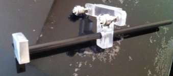
I don't have drawings of my first arm. I do for my 2nd buy would require access to a lathe and milling machine. These few pics are all I have as I have disassembled the arm now. That lat pic of the arm wand is not mine but mine is the same.
Rail is 25x3mm aluminium angle with 6mm pyres tubes glued with epoxy to inside of the L.
Arm wand is 6mm carbon fibre tube about 120mm long, carriage is 10mm polycarbonate or you could use acrylic, with MR104 bearings, and you will need to clean the grease out of the bearings.
The rail needs to be high enough to change LP's. have the arm wand as close to the underside of the rail as possible so it does not touch. The rail mount I used 3 M8 bolts to enable leveling of the rail. CW was made from an off cut of polycarbonate and secured with an M3 set screw. An M3 set screw was also used to secure the arm wand to the carriage.
Don't over think it just build it and develop from there
My first LTA was a simple affair, and quite easy to build. This simple arm bettered my Technics EPA100 in bass reproduction with the same cartridge mounted. I was surprised how good an arm made of basically scrap could be.
I don't have drawings of my first arm. I do for my 2nd buy would require access to a lathe and milling machine. These few pics are all I have as I have disassembled the arm now. That lat pic of the arm wand is not mine but mine is the same.
Rail is 25x3mm aluminium angle with 6mm pyres tubes glued with epoxy to inside of the L.
Arm wand is 6mm carbon fibre tube about 120mm long, carriage is 10mm polycarbonate or you could use acrylic, with MR104 bearings, and you will need to clean the grease out of the bearings.
The rail needs to be high enough to change LP's. have the arm wand as close to the underside of the rail as possible so it does not touch. The rail mount I used 3 M8 bolts to enable leveling of the rail. CW was made from an off cut of polycarbonate and secured with an M3 set screw. An M3 set screw was also used to secure the arm wand to the carriage.
Don't over think it just build it and develop from there
Attachments
Is a servo arm superior???? I guess that depends. The Dereneville I linked to the guy who developed it said the development cost was the price of a house in Germany. One of the challenges to overcome was servo motor noise into the audio signal. I also see this as the biggest hurdle to overcome in a DIY servo arm. Servos are easier now as you could buy the parts on eBay.
My first LTA was a simple affair, and quite easy to build. This simple arm bettered my Technics EPA100 in bass reproduction with the same cartridge mounted. I was surprised how good an arm made of basically scrap could be.
I don't have drawings of my first arm. I do for my 2nd buy would require access to a lathe and milling machine. These few pics are all I have as I have disassembled the arm now. That lat pic of the arm wand is not mine but mine is the same.
Rail is 25x3mm aluminium angle with 6mm pyres tubes glued with epoxy to inside of the L.
Arm wand is 6mm carbon fibre tube about 120mm long, carriage is 10mm polycarbonate or you could use acrylic, with MR104 bearings, and you will need to clean the grease out of the bearings.
The rail needs to be high enough to change LP's. have the arm wand as close to the underside of the rail as possible so it does not touch. The rail mount I used 3 M8 bolts to enable leveling of the rail. CW was made from an off cut of polycarbonate and secured with an M3 set screw. An M3 set screw was also used to secure the arm wand to the carriage.
Don't over think it just build it and develop from there
Thanks Warrjon, you mention you've dismantled, what are you using now please?
i am inclined to have a go, but don't want to trip over something you all have already solved! - my OL turntable doesn't have any arm board space that's connected, so can the LTA arm base be separated by the isolating feet from the table bearing or should it be connected like a pivot arm?
I ask this as when i mentioned maglev i understood firm mounting to be important, but what happens with air bearings, hence my mind mix!
Maglev does not have the platter floating all the commercial ones I have seen use maglev to reduce pressure on the bearing but the bearing still makes contact.
The LTA will need to be mounted firmly to the plinth so the bearing and arm are held rigid just like a pivoting arm.
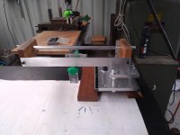
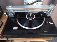
I am using my SP10 with the EPA100 while I rebuild the linear arm on my other SP10.
This is my current LTA.
The LTA will need to be mounted firmly to the plinth so the bearing and arm are held rigid just like a pivoting arm.
I am using my SP10 with the EPA100 while I rebuild the linear arm on my other SP10.
This is my current LTA.
Attachments
Apparently I have not been good enough explaining my ideas of a servo assisted linear tonearm. It dosen't fall into either of Niffy's categories. And it is not like the ones warrjon is pointing to.
My design is more like Ralfs :
A Revolutionary Pivoting Tangential Tone Arm
His "floating headshell" is in fact a small linear arm that only is supposed to move +/- 5mm or so, but perfectly tangential. It is only the groove that moves the cartridge in this small linear arm and when it starts to approach either end-stop the servo system (slowly) steps in and center the arm . No error correction in this system. In Ralfs case the servo is acting on a very complicated double pivot system, but in my case the servo acts as a linear arm. That also has the effect, that the distance from the cartridge to the solid , heavy servo sledge is very short as opposed to all the normal servo arms B&O Yamaha, rabco and the two warrjon points to. Revox has a little bit shorter arm, but if you make the servo system that relies on a correction of a angel error (the arm is a traditional pivoted arm that is corrected by the servo) you have to have a certain length from the pivot to the cartridge or else you get a servere angel error before the system can correct it.
In my case, you can make the arm as short as you like, just as the ones described by Niffy and warrjon , the only restriction here is the system that deals with warps (in Niffy's and warrjon's case a pivot)
I do not quite understad why the servo motor should be a source of noise. I have never heard about that in any of the commercial servo arms and if you study them, most of them dosen't have a very sophisticated motor system. I have had both a B&O 4004 and a Yamaha straight line tracker and there were absolutely no noise from the servos.
I still think that the small linear arm can be made lighter, with less friction and stiction , than in an arm that has to travel > 100 mm . The straightness of the material that forms the rail is a problem with long traveling arms.
My thoughts, and what I am working on now, is to use the principle of the l'il Caisey as the mechanism to deal with warps, but instead of having this outside the platter, it is placed right on top of the small linear arm and moved across the platter by the servo sledge. Therefore I call it a 3-D floating headshell...
I will try to come up with some drawings at a later time.
I hope that I have explained this in a way it is understandable..
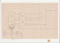
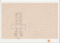
Here are two drawings of the 3-D floating headshell.
Only to show the principle, not to measure.
The linear moving part is shown as a L'il Caisey type, but it could be balls on stel/glas rods or whell on steel rod as well.
The mechanism that caries this over the platter moved by the servo motor, could be hovering over the platter while playing or outside the platter with a very solid arm to carry the 3-D floating headshell.
I have not included in the drawings the position detector, but it could be a hall effect device and a magnet, as in Ralphs arm or a photoelectric detector of some sort.
Attachments
I hope that I have explained this in a way it is understandable..
Yes, it is. Sorry to be a joy-killler, but nobody seems to realize that with this sort of servo assisted LT-s the "small" arm has to travel twice the distance than with a simple mechanical LT.
First the "small" arm moves 0.1 mm then the servo corrects and the arm moves backwards relative to the cradle. At the end, to travel 100 mm the arm has to travel 100 mm forth and 100 mm back is small increments.
Hi Koldby,
I get you. Basically exactly the same as the lil casey but with the rail being much shorter (quarter the length?). This would reduce the vertical mass of the arm. The high vertical mass was my main concern with the lil casey design, not that it appears to have negatively effected the versions made so far. Currently the lil casey will have lateral errors due to bearing friction as the carriage moves . Your servo will have bearing friction as the carriage moves and as the rail moves.
This type of servo definitely falls into the reactive camp. The effective masses are still seem by the cartridge.
Definitely an interesting take on the lil casey.
Niffy
Yes, it is. Sorry to be a joy-killler, but nobody seems to realize that with this sort of servo assisted LT-s the "small" arm has to travel twice the distance than with a simple mechanical LT.
First the "small" arm moves 0.1 mm then the servo corrects and the arm moves backwards relative to the cradle. At the end, to travel 100 mm the arm has to travel 100 mm forth and 100 mm back is small increments.
I am really not sure I understand what you are talking about. The cartridge only moves the small arm and cannot feel where it is relatively to the servo operated part. So how do you explain that it moves the double distance??
Hi Koldby,
I get you. Basically exactly the same as the lil casey but with the rail being much shorter (quarter the length?). This would reduce the vertical mass of the arm. The high vertical mass was my main concern with the lil casey design, not that it appears to have negatively effected the versions made so far. Currently the lil casey will have lateral errors due to bearing friction as the carriage moves . Your servo will have bearing friction as the carriage moves and as the rail moves.
This type of servo definitely falls into the reactive camp. The effective masses are still seem by the cartridge.
Definitely an interesting take on the lil casey.
Niffy
The movement of the small linear is only about +/- 5mm compared to the > 100 mm for the normal passive arm.
When you are talking about lateral errors in the L'il casey it is the bending of the cantilever you are referring to , right? So all arms will have this, more or less.
What I was talking about was that normal pivoted servo systems intentionally makes an angle error and then compensates for this. This is not the case with this arm AFAIK.
But if the definition of a reactive arm is that it dosent compensate for the effective masses, then I agree with you, this is a reactive arm.
My goal was to minimize the friction by reducing by an order of magnitude the length of the passive linear bearing and by reducing the weight of the moving parts. And at the same time make the distance from the cartridge tip to a solid mechanical ground (I see the servoarm/sledge as mechanical ground, because of the mass ratio between the 3-D headshell and the servoarm/sledge. The bearings for this is made very solid)
Thanks for the kind words and your fine analysis (as usual) of the servo systems
This may be off the topic.
Here are my thoughts on the floating headshells.
1. A floating headshell is basically a miniature linear arm. If the floating headshell uses regular ball bearings, it has all the disadvantages of a ball bearing linear arm. The purpose to make pin bearings is to get rid of ball bearings.
2. A miniature linear arm, i.e., a floating headshell, needs a mechanism to correct its positions constantly. If you can travel from A to B in a straight line, why do you need to travel in a curve as a pivot tangential arm?
Last edited:
Hi Koldby,
Your servo will have bearing friction as the carriage moves and as the rail moves.
Niffy
The only friction the cartridge can feel is the friction in the small arm bearings. The friction in the bearings in the servo sledge is dealt with by the motor and does not affect the cartridge. AFAIK
If you look at this video of Ralfs arm as it plays a record, you can see that the small linear bearing almost dosent move at all relative to the servo arm. I would think it would be far easier to make a bearing with such little movement frictionless (well almost) than a 100 mm long bearing.
YouTube
YouTube
This may be off the topic.
Here are my thoughts on the floating headshells.
1. A floating headshell is basically a miniature linear arm. If the floating headshell uses regular ball bearings, it has all the disadvantages of a ball bearing linear arm. The purpose to make pin bearings is to get rid of ball bearings.
2. A miniature linear arm, i.e., a floating headshell, needs a mechanism to correct its positions constantly. If you can travel from A to B in a straight line, why do you need to travel in a curve as a pivot tangential arm?
1. I am not suggesting ball bearings for the floating headshell
2. I am not correcting anything and especially not using a pivot. What the servo does is just moving the small linear arm over the platter in a straight line
The reason I was pointing at Ralfs arm was to show the principle in making a small linear arm and move it across the platter . I agree with you, that even though Ralfs arm is really beautiful and very well engineered it has the design issues as you point out. And further more the tangent the cartridge is following is a moving tangent in that design
Oh I think I see what Niffy and Alighiszem is getting at.
Niffy says that there is friction when the cartridge is moving and the servo arm is not and again when the servo arm is catching up with the cartridge eg. moving faster than the cartridge, and sort of the same is what Alighiszem is saying when he says it travels the double distance. But as far as I know servos, the servo system doesen't work this way it dosen't wait until the arm has moved a certain distance before it starts correcting. It is much more like it keeps the speed correctly. It is like an automatic speedcontrol. When it has reached the correct speed it stays there and only if there are some kind of deviation from that, it corrects. What about eccentricity then? But a passive arm also travels a longer distance then (back and forth) and has friction both ways. Again look at the video of Ralfs arm. there would be a wobbling back and forth in the floating headshell, if this discrete way of working was the case.
Niffy says that there is friction when the cartridge is moving and the servo arm is not and again when the servo arm is catching up with the cartridge eg. moving faster than the cartridge, and sort of the same is what Alighiszem is saying when he says it travels the double distance. But as far as I know servos, the servo system doesen't work this way it dosen't wait until the arm has moved a certain distance before it starts correcting. It is much more like it keeps the speed correctly. It is like an automatic speedcontrol. When it has reached the correct speed it stays there and only if there are some kind of deviation from that, it corrects. What about eccentricity then? But a passive arm also travels a longer distance then (back and forth) and has friction both ways. Again look at the video of Ralfs arm. there would be a wobbling back and forth in the floating headshell, if this discrete way of working was the case.
- Home
- Source & Line
- Analogue Source
- DIY linear tonearm