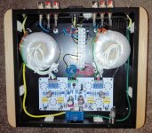
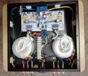
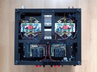
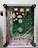
I'm working on PP EL 84 +ECC83 audio amplifier and toroidal transformers .") pictures attached .
pictures attached .
B.R. Alex
pictures attached . B.R. Alex
Attachments
-
 IMG_20200523_230657.jpg868.8 KB · Views: 894
 -
 IMG_20200523_230533.jpg661.2 KB · Views: 876
 -
 IMG_20200523_230647.jpg681.3 KB · Views: 836
 -
 IMG_20200523_232659.jpg583.5 KB · Views: 814
 -
 IMG_20200523_232721.jpg683.5 KB · Views: 765
 -
 IMG_20200523_232749.jpg508.5 KB · Views: 175
 -
 IMG_20200523_232800.jpg374.4 KB · Views: 161
 -
 IMG_20200523_232939.jpg584.3 KB · Views: 230
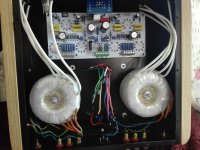
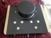
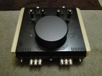
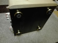
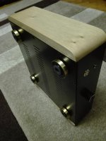
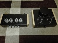
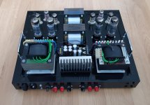
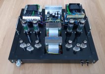
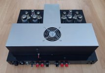
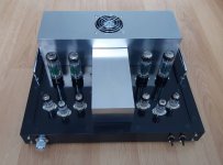
I'm working on PP EL 84 +ECC83 audio amplifier and toroidal transformers .
B.R. Alex
Beautiful congrats, so do you mean you did those toroidal ? ....all the best
Beautiful work!
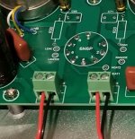
What is the material in the centre of the output toroids and what is it for?
Did you make the mains transformer cover yourself or purchase it?
plastic beads like those can be bought very cheap in bulk, it cuts down on how much of the much more expensive casting material you need.
my "old" 25W/4R PP UL after upgrading the driver stage PP-UL-EL34 - Google Photos
Attachments
Looks great. Good work.my "old" 25W/4R PP UL after upgrading the driver stage PP-UL-EL34 - Google Photos
THX
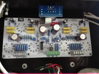
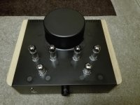
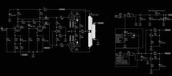
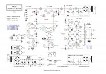
In fact this was a second modification. The original 2005 version was a copy of the Audio Innovations 800 mk3. Later I changed the output biasing from auto to fixed and wound new OTRs. Now, the new driver uses two tubes instead of two and half. The first one is a totem pole amplifier. The second implements a DC coupled LTP phase inverter supported by CCS.
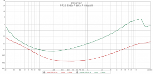
Distortion seems to me quite high at higher power levels and frequencies. WDYT ?
In fact this was a second modification. The original 2005 version was a copy of the Audio Innovations 800 mk3. Later I changed the output biasing from auto to fixed and wound new OTRs. Now, the new driver uses two tubes instead of two and half. The first one is a totem pole amplifier. The second implements a DC coupled LTP phase inverter supported by CCS.
Distortion seems to me quite high at higher power levels and frequencies. WDYT ?
Attachments
Last edited:
Distortion seems to me quite high at higher power levels and frequencies. WDYT ?
Are those measurements with or without feedback?
If it's without maybe they're not too bad.
It looks like you're using REW. I didn't know you could put different power levels on the same plot. I'll have to investigate that.
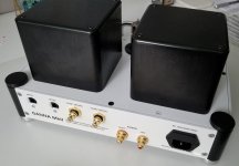
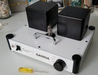
Finished my pandemic-work-at-home project this week: DAC upgrade. Change digital receiver to AK4113 to enable 192kHz decoding, added digital input selector and went from 2x 6S31B to a single 6N6P for the output stage. The DAC itself has not changed: 2x PCM1704 working differentially on Sowter 9055 transformer and Sowter 9040 output transformer. Also tried a 'single-board' approach for this design and found it extremely convenient and useful.
Very pleased overall with the sound!
Mess with red-white output RCA jacks has been already corrected
Very pleased overall with the sound!
Mess with red-white output RCA jacks has been already corrected
Attachments
Last edited:
Finished my pandemic-work-at-home project this week: DAC upgrade. Change digital receiver to AK4113 to enable 192kHz decoding, added digital input selector and went from 2x 6S31B to a single 6N6P for the output stage. The DAC itself has not changed: 2x PCM1704 working differentially on Sowter 9055 transformer and Sowter 9040 output transformer. Also tried a 'single-board' approach for this design and found it extremely convenient and useful.
Very pleased overall with the sound!
Mess with red-white output RCA jacks has been already corrected
Did have a close look at your PCB and am I correct that the two heater pins are still to be connected?
I correct that the two heater pins are still to be connected?
I did think of using a tube with radioactive isotope heating but, unfortunately ran out...
I am not sure what are you referring to exactly, but there are two test points marked Heat1 and Heat2 for monitoring the tube heater power rail. Could it be that is what you saw? I did put quite a few of test points here and there just for the sake of not pulling the schematics every time I need to do measurements, maintenance, etc. The circuit routing itself is done on the bottom of the PCB.
And empty footprints are for the option of loading the 9055 on the secondary side. Brian Sowter said the sound may change if one does so and I reserved this option in the case I get bored again...
Attachments
Finished my pandemic-work-at-home project this week: DAC upgrade. Change digital receiver to AK4113 to enable 192kHz decoding, added digital input selector and went from 2x 6S31B to a single 6N6P for the output stage. The DAC itself has not changed: 2x PCM1704 working differentially on Sowter 9055 transformer and Sowter 9040 output transformer. Also tried a 'single-board' approach for this design and found it extremely convenient and useful.
Very pleased overall with the sound!
Mess with red-white output RCA jacks has been already corrected
That is one pretty DAC, do you have a link to more info?
That is one pretty DAC, do you have a link to more info?
Would be glad to help, what it is that you'd like to know?
I am using a bunch of not in production components here, that are key ones for the quality of the sound - the PCM1704, the 9055 so it is definitely a design tuned to the on-hand inventory. But the digital receiver and channel selection part is all up-to-date.
I did think of using a tube with radioactive isotope heating but, unfortunately ran out...
I am not sure what are you referring to exactly, but there are two test points marked Heat1 and Heat2 for monitoring the tube heater power rail. Could it be that is what you saw? I did put quite a few of test points here and there just for the sake of not pulling the schematics every time I need to do measurements, maintenance, etc. The circuit routing itself is done on the bottom of the PCB.
And empty footprints are for the option of loading the 9055 on the secondary side. Brian Sowter said the sound may change if one does so and I reserved this option in the case I get bored again...
Ah, I see that is it.
Thanks for the explanation!
Would be glad to help, what it is that you'd like to know?
I am using a bunch of not in production components here, that are key ones for the quality of the sound - the PCM1704, the 9055 so it is definitely a design tuned to the on-hand inventory. But the digital receiver and channel selection part is all up-to-date.
Ahhhh too bad I see that most of those chips are not realistically available anymore. Due to how tidy it looks I thought it was a project that is easy to reproduce. That, and well just curiosity for how it all works so no real specific questions
Very nice build though
- Home
- Amplifiers
- Tubes / Valves
- Photo Gallery