Thanks for the positive feedback guys! Much appreciated.
I won't make any decisions about processing until I see what they do in a measurement. Though I will say that I'm hoping to shave off about 6 dB of the array's bottom end, while keeping them mostly full range and make up for that with the subs. The goal is to get more uniform balance left to right down to an even lower frequency. Right now that balance is made by shifting energy in the arrays below about 80 Hz. I'm hoping to make up for that with the subs instead.
I still have to see measurements first to know how high in frequency these subs can support the arrays. As long as they are down far enough by ~900 Hz, whose 3rd harmonic is responsible for that nasty peak at ~2700 Hz. So in theory they can run up to about ~200 Hz as helper woofers for the arrays.
Some more inner details I've been working on.
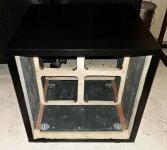
As mentioned a bit earlier in this thread, the inner walls of the enclosure have been covered with MLV.
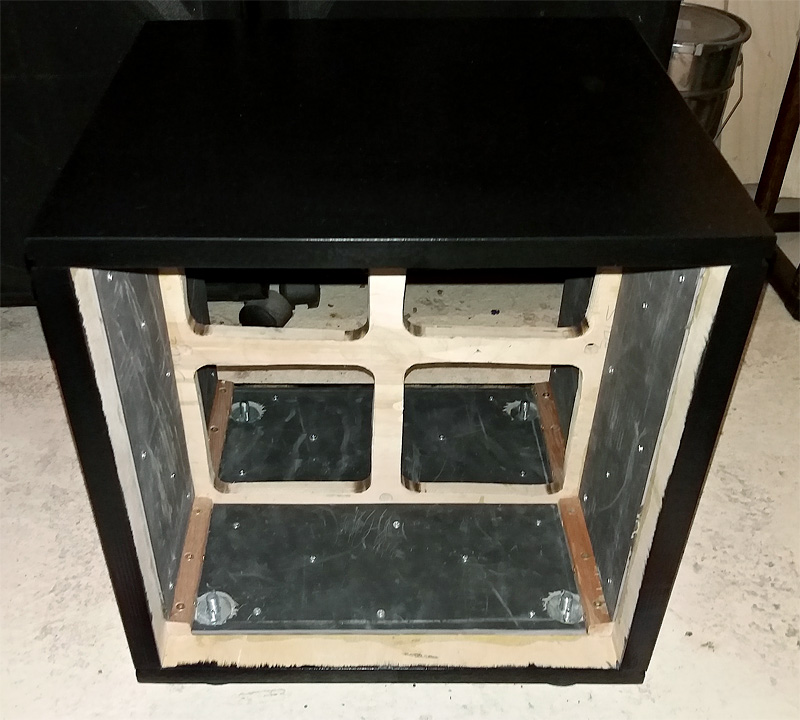
Making all the walls approximately one Inch in thickness...
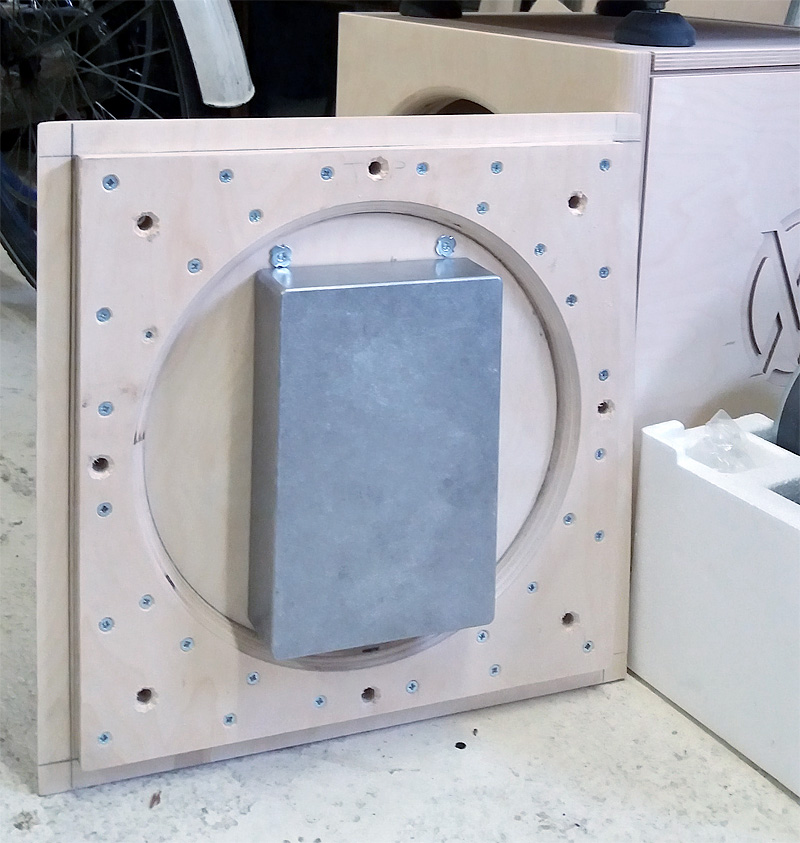
The aluminium box, protecting the amplifier also got a cover-up with MLV:
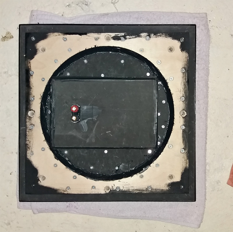
The speaker-out are in place as well as a ground connection (not seen here).
The way it looked before:
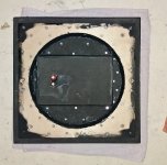
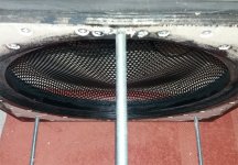
And finally a detail of the protection screen, as seen from the inside:
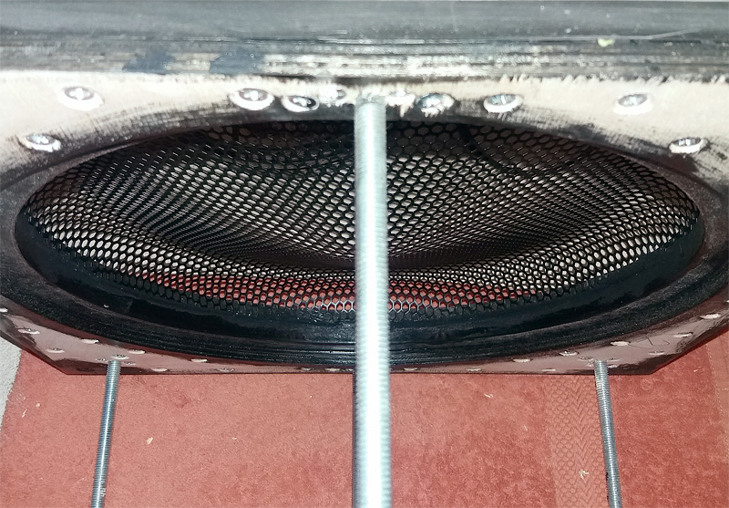
Hardly visible, the screen is sunk into the baffle by a couple of mm and glued in place.
The same rubbery glue was used to seal off the corners of the aluminium cover.
Almost ready to start impedance measurements. Sadly I ran out of time as the old laptop wouldn't work with me today. That's a job for next weekend.
Then on to finishing the amplifier connections etc...
I did say I would take my time .
.
As mentioned a bit earlier in this thread, the inner walls of the enclosure have been covered with MLV.
Making all the walls approximately one Inch in thickness...
The aluminium box, protecting the amplifier also got a cover-up with MLV:
The speaker-out are in place as well as a ground connection (not seen here).
The way it looked before:
And finally a detail of the protection screen, as seen from the inside:
Hardly visible, the screen is sunk into the baffle by a couple of mm and glued in place.
The same rubbery glue was used to seal off the corners of the aluminium cover.
Almost ready to start impedance measurements. Sadly I ran out of time as the old laptop wouldn't work with me today. That's a job for next weekend.
Then on to finishing the amplifier connections etc...
I did say I would take my time
.Attachments

The Norwegian guy's system earlier pointed to in this thread ... He claims he gets way more of the the Vifa TG9 equipped linesources when he is not running them full-range. In his case, it's claimed that removing the low bass from the fullranges takes them significantly up a notch in many levels ... an it's claimed that is not subtle at all.
@halair listened to those and he may possibly shed some more light onto this
I have never been able to a/b test this but I assume this should be pretty easy to verify with measurements too...
Just a thought
@halair listened to those and he may possibly shed some more light onto this
I have never been able to a/b test this but I assume this should be pretty easy to verify with measurements too...
Just a thought
Last edited:
I can 2nd that based on my SB65 arrays crossed to mono subs at 100 Hz. I noticed a distinct improvement moving sub XO from 80 to 100 Hz and from 12 db to 24 db filter slope. But SB65's need more help than TC9s...(well 24 TC9s have (only) 30% more displacement than 32 SB65s)
One of the things to look at is at what frequency does the array THD start to rise and start helping the arrays there. Another consideration is reducing modulation distortion by keeping the ULF entirely out of the arrays. Neither of these means the (stereo) subs can't have a low slope high pass filter and contribute above where the arrays are high-passed
One of the things to look at is at what frequency does the array THD start to rise and start helping the arrays there. Another consideration is reducing modulation distortion by keeping the ULF entirely out of the arrays. Neither of these means the (stereo) subs can't have a low slope high pass filter and contribute above where the arrays are high-passed
I have listened to Adyton Imagic 2.0 which utilize 18x TG9´s and a ribbon tweeter. For the low end 8x 13" was used, configured in two towers.
In this arrangement there is no EQ done on the TG9´s IIRC, simply supported by the tweeter with its own LF shading.
The room the Imagic was placed in was large, probably 50sq.m and 3m ceiling height. Its also probably 4 years ago and I cant recall details, except it played very nice indeed. No lack of dynamics there
In this room, both the bass and Imagic is considered a finite array, and with a point source tweeter, the way it integrate with the room is very different than an infinite array do, as the latter create a nearfield area within the entire room, assuming normally sized rooms.
Leaving the TC/TG9 of job duties below Fs (125hz) will obviously relieve them from the high energy work load this freq.range. I have no doubt they will be "less stressed" with a dedicated bass system assisting them.
The whole idea of this project, the full range arrays was to play with a crossoverless system. Which worked out beyond my expectations.
I have no doubt adding subwoofers will change what I get to hear. But it will be difficult to compare one on one. You can rest assured that I will try a lot of things over time. I do have hopes this will lift up performance in the midrange too. But I do not count on that. I'll just be happy and thrilled if it happens, but not disappointed if it doesn't, as I'm quite pleased (thrilled actually) with what I've got.
I got lucky with room gain within my relatively small room. It still is hard to believe what I get down low with these little drivers. I will definitely try and have the subs do the (heavy) lifting in the first octave. But even more than that I do hope to make progress in the left/right channel balance.
All these factors no doubt will play a role in perception.
The primary reason for the subs: create headroom. Above 200 Hz there is a lot of headroom available. Below that, it still is the room that plays a huge role in what I can and can't do. If I can make some progress there I'm pretty sure the total experience will be improved too. After all I do ask those small drivers to do a lot. Adding 2/3 rds in volume displacement capacity should do something, right?
What I get right now at the listening spot is carefully planned.(*) I've tried to make sure the room and speaker are working together as best as I can get them to. I've used all ideas I could come up with to get that to work. And it does work, at least I'm happy and that's what counts.
(*) within the restrictions I had to work with. Inside a dedicated room there would have been more options to play with.
Lots of words to describe my sentiments, I guess what I'm saying here is: We'll see (or hear). But I am optimistic about it. You can see I do have some trust in that, by the level of finish of (and dedication I put into) the subs. If it were a mere experiment I would have build some simple boxes to try the concept first. If only I could have used bass towers, but we can't have it all I guess.
I have no doubt adding subwoofers will change what I get to hear. But it will be difficult to compare one on one. You can rest assured that I will try a lot of things over time. I do have hopes this will lift up performance in the midrange too. But I do not count on that. I'll just be happy and thrilled if it happens, but not disappointed if it doesn't, as I'm quite pleased (thrilled actually) with what I've got.
I got lucky with room gain within my relatively small room. It still is hard to believe what I get down low with these little drivers. I will definitely try and have the subs do the (heavy) lifting in the first octave. But even more than that I do hope to make progress in the left/right channel balance.
All these factors no doubt will play a role in perception.
The primary reason for the subs: create headroom. Above 200 Hz there is a lot of headroom available. Below that, it still is the room that plays a huge role in what I can and can't do. If I can make some progress there I'm pretty sure the total experience will be improved too. After all I do ask those small drivers to do a lot. Adding 2/3 rds in volume displacement capacity should do something, right?
What I get right now at the listening spot is carefully planned.(*) I've tried to make sure the room and speaker are working together as best as I can get them to. I've used all ideas I could come up with to get that to work. And it does work, at least I'm happy and that's what counts
.(*) within the restrictions I had to work with. Inside a dedicated room there would have been more options to play with.
Lots of words to describe my sentiments, I guess what I'm saying here is: We'll see (or hear)
. But I am optimistic about it. You can see I do have some trust in that, by the level of finish of (and dedication I put into) the subs. If it were a mere experiment I would have build some simple boxes to try the concept first. If only I could have used bass towers, but we can't have it all I guess. As it was kinda chilly outside I took this day off from working in the garage and fixed my impedance rig in the comforts of home. All is working fine again so I can move on to measuring the impedance of the subwoofer. I'll test free impedance, impedance in box without stuffing and with stuffing to see what I can get.
I previously used bitumen for damping but I don’t know what MLV is, sorry for my ignorance but would you have a chance to elaborate?
And how thick layers of MLV did you use?
I think we can have it all .... if we decide for it and don’t look back
And how thick layers of MLV did you use?
.......If it were a mere experiment I would have build some simple boxes to try the concept first. If only I could have used bass towers, but we can't have it all I guess.
I think we can have it all .... if we decide for it and don’t look back
Last edited:
It is Mass Loaded Vinyl, to be specific, this stuff: https://www.merford.com/media/202645/isomat-ts.pdf
I used the 3.5 mm and 6 mm versions (had lots of leftovers from old projects and ordered the 6 mm for this one).
Look at the graphs to see how it functions as a soundblocker. I also used it to add weight to the enclosure walls.
WEIGHT in kg / m 2
5 kg / m 2 (thickness 2.1 mm).
8 kg / m 2 (thickness 3.5 mm).
14 kg / m 2 (thickness 6 mm).
Specific mass: 2.4 kg / m 2
I used the 3.5 mm and 6 mm versions (had lots of leftovers from old projects and ordered the 6 mm for this one).
Look at the graphs to see how it functions as a soundblocker. I also used it to add weight to the enclosure walls.
Last edited:
It is Mass Loaded Vinyl, to be specific, this stuff: https://www.merford.com/media/202645/isomat-ts.pdf
I used the 3.5 mm and 6 mm versions (had lots of leftovers from old projects and ordered the 6 mm for this one).
Look at the graphs to see how it functions as a soundblocker. I also used it to add weight to the enclosure walls.
Dutch and Norwegians are closer than you think.... I seem to understand quite a lot of the Dutch text without google translate...
I believe this is really effective in lowering the resonance frequency of the panels and damping the resonances. It looks somewhat similar to what Piega is using in their cabinets. There was a video somewhere of Kurt Scheuch demonstrating the resonances with and without. The bare cabinet without damping rings like a bell, with the damping it is close to dead silent. I searched for the video but can’t find it now.
I assume with MDF and HDF it would be really efficient too, question is how much is needed and how many layers?
Last edited:
That was the idea . Dissimilar materials put together often work better than each of them by itself. I wanted to add some weight (to offset the moving mass) and also wanted to preserve as much inner space as possible. The MLV is very heavy for the space it occupies.
I'll try and get the inner space "virtually bigger" again with damping material (by adding fiberglass fill with wool felt to seal it off from the driver area).
The threaded rods allow me to put some pressure on the enclosure and I guess if I were interested in doing so I could tune it somewhat.
MLV is dead weight though. It doesn't go back to it's original shape after compressing it. So my MLV seals could loosen over time. I'll seal the enclosure with Butyl rope. That way I can disassemble it if there is a need for that. I like my constructions to be accessible for maintenance.
You've asked an engineer and he did answer.
To really act as a sound barrier the MLV would ideally be free to move, not glued but with some space between on both planar sides with something like neoprene to allow it to do so. That would have taken up too much space. So I use it much like bitumen often is used, though I dislike bitumen as it fumes and gets brittle over time. Butyl has been used extensively to replace bitumen as part of CLD solutions. What I did isn't CLD, just adding dead weight and hoping to preserve some "sound blockage" function.
MLV can be used in walls as a limp mass, it also is quite popular in Car Audio.
(I have it inside the doors of my car and on the firewall blocking engine sound, there it is free to move. Crazy huh? to block that great sound a flat 6 makes)

More info here...
. Dissimilar materials put together often work better than each of them by itself. I wanted to add some weight (to offset the moving mass) and also wanted to preserve as much inner space as possible. The MLV is very heavy for the space it occupies.I'll try and get the inner space "virtually bigger" again with damping material (by adding fiberglass fill with wool felt to seal it off from the driver area).
The threaded rods allow me to put some pressure on the enclosure and I guess if I were interested in doing so I could tune it somewhat.
MLV is dead weight though. It doesn't go back to it's original shape after compressing it. So my MLV seals could loosen over time. I'll seal the enclosure with Butyl rope. That way I can disassemble it if there is a need for that. I like my constructions to be accessible for maintenance.
You've asked an engineer and he did answer
.To really act as a sound barrier the MLV would ideally be free to move, not glued but with some space between on both planar sides with something like neoprene to allow it to do so. That would have taken up too much space. So I use it much like bitumen often is used, though I dislike bitumen as it fumes and gets brittle over time. Butyl has been used extensively to replace bitumen as part of CLD solutions. What I did isn't CLD, just adding dead weight and hoping to preserve some "sound blockage" function.
MLV can be used in walls as a limp mass, it also is quite popular in Car Audio.
(I have it inside the doors of my car and on the firewall blocking engine sound, there it is free to move. Crazy huh? to block that great sound a flat 6 makes
)
More info here...
Last edited:
You really seem to have control and thought about everything here
With regards to damping I have read that KEF is using some sort of carbon based open foam that serve as damping and it actually supposedly makes the volume drivers see 25% larger than the physical volume of the box .... I have never seen that available on the open market though. guess it is KEF internal only ...
And how about the ceramics foam that Audio Physic is using?
It is supposedly doing some of the same things... most importantly it is said not to kill dynamics the way regular damping material may do .... in the article below they are focusing lots on bracing, but from what I understand there should be some absorption characteristics, I may be wrong though ... If I am not fully incorrect, the only damping material in woofer cabinets in the reference Plus+ series of loudspeakers is ceramic foam. I talked to Dieter Kratochwil at Audio Physic and that’s what he told me
Ceramic Foam Bracing |
The only thing I found reminding of this are these, small size and pretty hefty price
100mm Waben Keramik, Schaum Keramik, Keramik Filter, Hohe Temperatur Bestandig Zirkonia-in Klimaanlage Teile aus Haushaltsgerate bei AliExpress
It is quite similar I believe as Audio Physic guys state what they are using is originally designed as ceramic filters ...
Did anyone try or check out any of these things?
Last edited:
The activated coal from Kef, Yes, I've read about that one.
That other material from Audio Physic is nice too! What a way to make braces!
About the dynamics? That may stir up an entire discussion but I don't feel that way as I do not rely on a driver to hold the frequency curve by itself (as I do use EQ for that).
What I do find important is to check impedance while stuffing as that shows us a lot. Measurements go above listening preference here for me. One can see the damping properties in the impedance curve. You can see when it is too much stuffing or not enough. There too, dissimilar materials can complement each other.
For the arrays a combination of Angel Hair and Fiberglass worked very well. Better than either of them could do by itself. However I was able to get the same results by combining wool felt and fiberglass. As the Angel Hair I had (raw product sourced from the production plant, as I used to work there I had connections) was unprocessed and still needed a lot of work to make it ready for filling a cabinet.
For the arrays I've played with Angel Hair which really is as good as advertised for midrange frequencies. However the old fashioned Fiberglass fill still is excellent for low frequency (it is valid for a wide range of frequencies actually) though is is way less spectactuary priced and named.
Wool felt (the real kind) is kind of special too. For closed cabinets both fiberglass fill and wool felt are still my "go to" materials. I was very disappointed with the performance of polyfill specifically advertised for it's audio properties. Here fiberglass walks all over it. (at least in my experience and experiments)
I wouldn't use fiberglass in a ported enclosure though, but then again, I wouldn't use ported enclosures anyway. I may consider using an aperiodic vent, though not in this build.
That other material from Audio Physic is nice too! What a way to make braces!
About the dynamics? That may stir up an entire discussion but I don't feel that way as I do not rely on a driver to hold the frequency curve by itself (as I do use EQ for that).
What I do find important is to check impedance while stuffing as that shows us a lot. Measurements go above listening preference here for me. One can see the damping properties in the impedance curve. You can see when it is too much stuffing or not enough. There too, dissimilar materials can complement each other.
For the arrays a combination of Angel Hair and Fiberglass worked very well. Better than either of them could do by itself. However I was able to get the same results by combining wool felt and fiberglass. As the Angel Hair I had (raw product sourced from the production plant, as I used to work there I had connections) was unprocessed and still needed a lot of work to make it ready for filling a cabinet.
For the arrays I've played with Angel Hair which really is as good as advertised for midrange frequencies. However the old fashioned Fiberglass fill still is excellent for low frequency (it is valid for a wide range of frequencies actually) though is is way less spectactuary priced and named
.Wool felt (the real kind) is kind of special too. For closed cabinets both fiberglass fill and wool felt are still my "go to" materials. I was very disappointed with the performance of polyfill specifically advertised for it's audio properties. Here fiberglass walks all over it. (at least in my experience and experiments)
I wouldn't use fiberglass in a ported enclosure though, but then again, I wouldn't use ported enclosures anyway. I may consider using an aperiodic vent, though not in this build.
Last edited:
That ceramic foam would be especially great if it could be cast in place. I wonder if one buys it in slabs and machines to shape or if custom castings are required. Also possibly useful as an acoustic resistance element that didn't change shape or characteristics over time.
Do you have any data on the acoustic performance of wool felt, flow resistitivity would be a great but anything related loss vs frequency for a given thickness.
I've been using felt where I don't have room for enough fiberglass to do any good - like on the wall behind the drivers in my arrays. But the remainder of the cabinet is fully stuffed with fiberglass. I don't think you can put too much in unless so much its highly compressed.
I don't have any data on the wool felt, except for what I measured inside my enclosure.
You can actually stuff too much, quite easy to see in impedance graphs. But if it isn't compressed, it probably isn't too much.
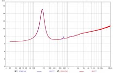
Here's a comparison between wool felt and an empty box:
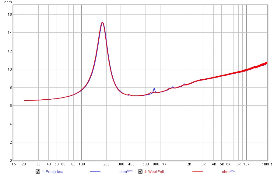
Wool felt on all walls only. About 7mm in thickness. Still smells like sheep.
(obviously this isn't the subwoofer (lol))
You can actually stuff too much, quite easy to see in impedance graphs. But if it isn't compressed, it probably isn't too much
.Here's a comparison between wool felt and an empty box:
Wool felt on all walls only. About 7mm in thickness. Still smells like sheep
.(obviously this isn't the subwoofer (lol))
Attachments
Last edited:
I have been looking for ways to get hold of larger batches of that ceramic foam, I believe there are some Swiss and German, looks like US too, companies doing this.... I found no place to buy larger pieces .... research still in progress
Ceramic Foams | EngiCer SA
SIVEX Ceramic Foam Filters | Pyrotek
Ceramic Foam Filter | FoamPartner
Isn’t it so that one of the main thing you need to look for is small ripples in impedance curve, as this is sign of standing waves backfiring onto drivers.... At least from my talks to different guys within the industry, the main trouble with closed boxes is the backfiring onto the drivers that provide a delayed distorted signal, more important than how the impedance with the resonance behaves; Just wonder how we can understand this as I really don’t know how to best deal with that
Last edited:
Yes, that was my lesson too. Little wiggles usually lead to frequency anomalies (reflections back to the cone).
I've gone trough great length to avoid all those small wiggles. It's all here in this thread, where I chased it down even up to the smallest wiggles.
Another goal was to bring down the impedance peak and have it move as far to the left as possible for the arrays. This is what influences the knee, the place where the driver will start it's natural roll off.
Here's an example taken of my test enclosure. What you see is the driver free on baffle, driver in box and driver in box fully damped:
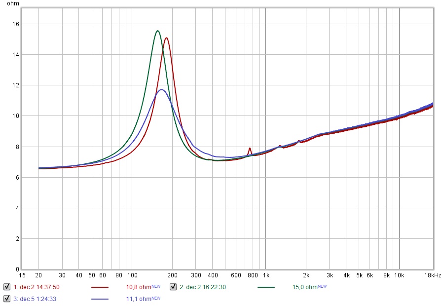
See how the peak of blue curve is between the green (free air) and red (driver in empty box)?
The combined array even featured a lower total impedance than this test enclosure.
By the way, this test enclosure now functions as a reference for my subwoofer impedance tests.
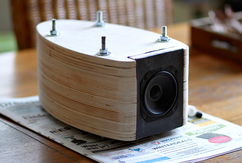
I ran the first tests today, I'm preparing to seal up the sub for the empty box tests. But I had to paint the bolts that hold the subwoofer (paint it black) first!
Little wiggles usually lead to frequency anomalies (reflections back to the cone).I've gone trough great length to avoid all those small wiggles. It's all here in this thread, where I chased it down even up to the smallest wiggles.
Another goal was to bring down the impedance peak and have it move as far to the left as possible for the arrays. This is what influences the knee, the place where the driver will start it's natural roll off.
Here's an example taken of my test enclosure. What you see is the driver free on baffle, driver in box and driver in box fully damped:
See how the peak of blue curve is between the green (free air) and red (driver in empty box)?
The combined array even featured a lower total impedance than this test enclosure.
By the way, this test enclosure now functions as a reference for my subwoofer impedance tests.
I ran the first tests today, I'm preparing to seal up the sub for the empty box tests. But I had to paint the bolts that hold the subwoofer (paint it black
) first!Attachments

Last edited:
Looks interesting, your tests ... but I assume we need to listen too for things we can‘t measure, and how do we know that we killed enough of the reflections backfiring through drivers ... Peter Lyngdorf is advocating open baffle a lot because this phenomenon does not exists there. However, if we could kill those backfiring things enough; I suppose looking at impedance curves is simply just not enough
I don't feel that way at all! That wave front from an open baffle is coming back to haunt you too! And it doesn't even have to go through the cone.
I'm pretty sure most OB fanatics actually like that delayed back wave, after it hit the wall behind the speakers. It is part of the total experience.
The impedance curve shows more than you'd imagine. You can even see ripple if there are stray sounds while making a measurement. It is an excellent tool to use.
The biggest problem of closed box speakers isn't the boxy sound. It is the lack of those delayed waves bouncing back to conceal the cross talk happening at your ears from both the left and right speaker. You won't notice that effect as much with OB speakers. But that's because it has those (delayed) reflections as part of it's signature sound. Take them outside or absorb that back-wave and I'm pretty sure they will start to resemble the sound of a good behaving closed box.
A bold thing to say huh?
But just measure at ear positions to "see" what I'm talking about. It is the reason for my mid-side EQ adventure (and many more experiments).
There isn't much we can't measure, there still is a lot to learn too. Like how to interpret the measurements and know what we "hear" into that.
Chances are that people that claim too much damping "kills the sound" actually like what they get back through the cone (messing up the frequency response). How many times have you read EQ made the speakers sound boring or dull? That doesn't mean it has to be that way, I promise! We just need to learn more and work harder to understand what it is we hear. That is part of the fun for me.
Last edited:
- Home
- Loudspeakers
- Full Range
- The making of: The Two Towers (a 25 driver Full Range line array)