For the SMD parts, IC1 can be e.g. CNY173SR2VM from On Semi.
Vishay equivalent will of course also do.
R6 can be any 1206 thin film, e.g. Beyschlag MMA02040C1000FB000 (MELF).
For C2, I would prefer a film cap, such as WIMA MKS2B051001N00JSSD.
But they are quite expensive from Mouser.
So you might want to use a electrolytic cap instead, e.g. Nichicon UKZ1H220MPM.
Patrick
Cheers Patrick! 1206 on the resistor (I've been meaning to buy a smd resistor pack for a while actually, and build some smd skills). Re the cap, I'll probably try and use something on hand (i have some film in the right value but not footprint), but I can make that work.
")
I've sourced some of the optos already (CNY17-3S-TA1 - Lite-On - Optocoupler) from ebay.
So, with 5 pcbs on the way, I'll give two away to ZUM, build one using IRFP150's and make sure everything works, and keep two for the eventual Semisouth GB to finish.
Looking forward to it!
You will need to change the value of R3 if you use any other devices then the Semisouths.
The Semisouths have a Vgs at 1.2A of ~1.2V.
The IRFP150 ~4V. 2SK3497 ~2.5V.
The closest (as well as negative tempco) would be 2SK1058 at ~2V Vgs.
BUT 2SK1058 is NOT pin compatible.
Patrick
.
The Semisouths have a Vgs at 1.2A of ~1.2V.
The IRFP150 ~4V. 2SK3497 ~2.5V.
The closest (as well as negative tempco) would be 2SK1058 at ~2V Vgs.
BUT 2SK1058 is NOT pin compatible.
Patrick
.
Attachments
805 and 1206 packages are not a problem for hand soldering, even with wire solder.
I have failed in the past with PCM1794, but fulfilling Sjostrom's QRV-08 headphone amp was pretty straightforward.
When you hand solder those smd packages you flux and solder the pads first before placing the device (a small amount,not a big blob).Then you flux those pads and place the device,hold it down with tweezers and come in from each end with your iron,use 63/37 solder.
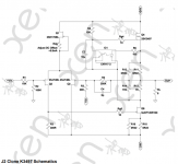
Just having a wee think about the schematic from EVUL.
A question please? I would have imagined that R3 would equal R1 and R4 would be 100K in order for the rolloff of the -Vin frequency would match that of +Vin, as well as the impedance seen by -Vin would be the same as +Vin, and the ratio for the feedback would be maintained? I'm clearly wrong in that thinking, but I'll be stuffed if I know why!
Could anyone explain it to me? Much appreciated in advance.
Attachments
Last edited:
> And just noticed there's 2 x R3 on the silkscreen and schematic.
My mistake. Sorry for that. I'll revise pdf and Gerber later.
Let's rename the one connected to -Vs as R33.
On the PCB, this is next to R16, and the nominal value is 300R.
You might need to reduce this to 270R or even 240R for some power JFETs with lowish Vgs (~1V).
> I would have imagined that R3 would equal R1 and R4 would be 100K
> as well as the impedance seen by -Vin would be the same as +Vin, ....
IF you use the amplifier with single ended input, i.e. -Vin = 0V, then R3 should be 10k, R4 should be 100k.
IF however you are using symmetrical inputs, i.e. -Vin = -(+Vin), then those value as published will load the source symmetrically.
You can figure this out by running the Spice files published before, and look at current amplitudes through R1 and R3.
Those spice files are using symmetrical inputs, as I would.
Patrick
Last edited:
> And just noticed there's 2 x R3 on the silkscreen and schematic.
My mistake. Sorry for that. I'll revise pdf and Gerber later.
Let's rename the one connected to -Vs as R33.
On the PCB, this is next to R16, and the nominal value is 300R.
You might need to reduce this to 270R or even 240R for some power JFETs with lowish Vgs (~1V).
> I would have imagined that R3 would equal R1 and R4 would be 100K
> as well as the impedance seen by -Vin would be the same as +Vin, ....
IF you use the amplifier with single ended input, i.e. -Vin = 0V, then R3 should be 10k, R4 should be 100k.
IF however you are using symmetrical inputs, i.e. -Vin = -(+Vin), then those value as published will load the source symmetrically.
You can figure this out by running the Spice files published before, and look at current amplitudes through R1 and R3.
Those spice files are using symmetrical inputs, as I would.
Patrick
Hey, not a problem, and that's what I volunteered to do when I got some made. I shared on the forum so everyone else could see too.
Now I have to work out the 'why' of your explanation.
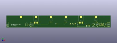
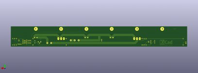
well, i'll go have a play and see how it ends up.I'm going to order up a set of these boards for myself. If anyone else is interested, give a shout.
The LTP layout is for a pair of SJ109s (although 4 SJ74s can be inserted in the same holes); the CCS layout is for a pair of SK170s.
Note that they'll be on the expensive side as they're large, I'm getting them done at EuroCircuits rather than a Chinese board house, and volume is likely to be no more than a handful.
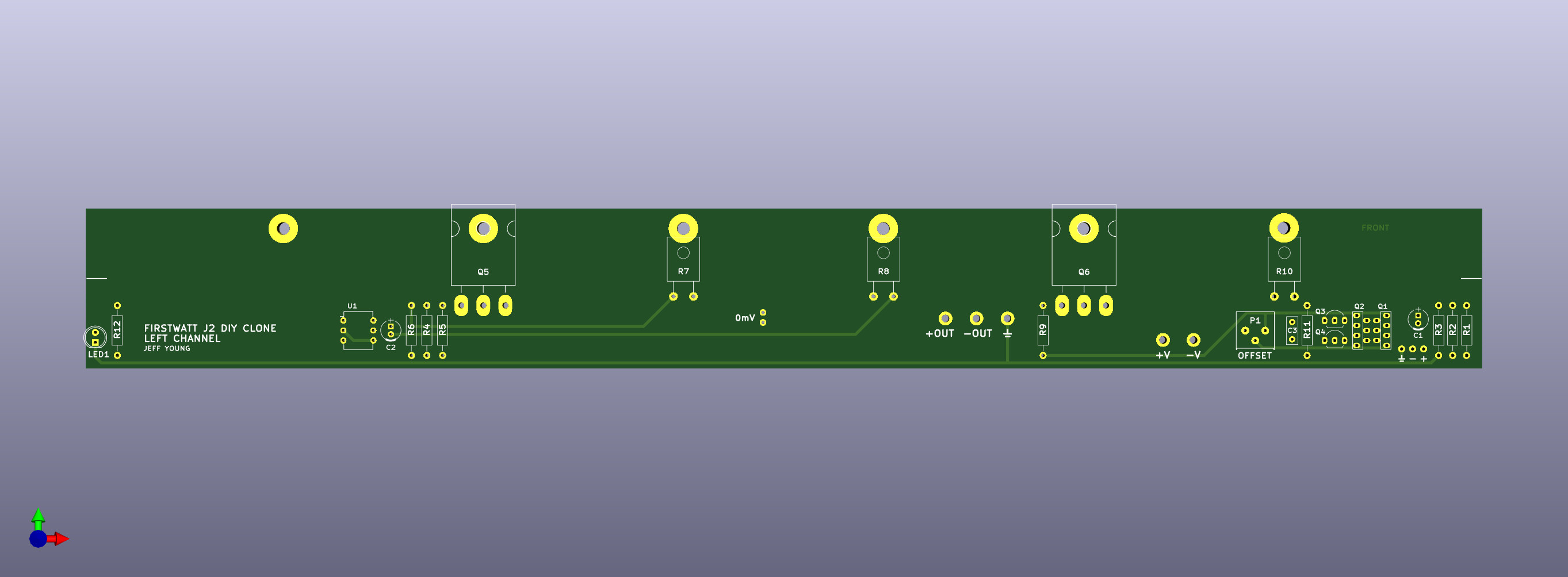
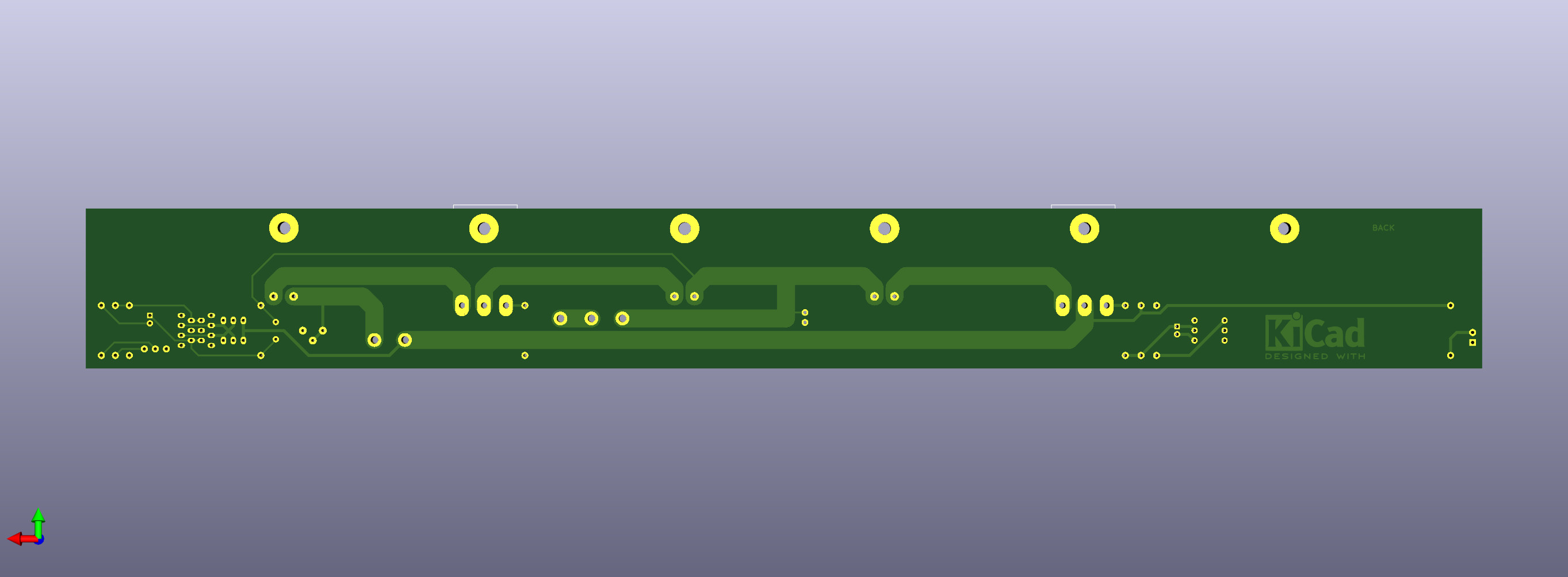
Cheers,
Jeff.
The LTP layout is for a pair of SJ109s (although 4 SJ74s can be inserted in the same holes); the CCS layout is for a pair of SK170s.
Note that they'll be on the expensive side as they're large, I'm getting them done at EuroCircuits rather than a Chinese board house, and volume is likely to be no more than a handful.
Cheers,
Jeff.
Attachments
I am interested in a set.
I'm going to order up a set of these boards for myself. If anyone else is interested, give a shout.
The LTP layout is for a pair of SJ109s (although 4 SJ74s can be inserted in the same holes); the CCS layout is for a pair of SK170s.
Note that they'll be on the expensive side as they're large, I'm getting them done at EuroCircuits rather than a Chinese board house, and volume is likely to be no more than a handful.
Cheers,
Jeff.
Jeff, would you mind telling us about the dimensions of the board?
Cheers, Ernst
Last edited:
- Home
- Amplifiers
- Pass Labs
- FirstWatt J2