If I get it right, you've arranged the output and input terminals quite close to each other at the PCB's bottom right corner, as shown in the pics. In addition, the output inductor comes close to the input coupling capacitor. Maybe the few pF's between these components are enough to turn a high bandwith amplifier like the HB into a power oscillator.
Best regards!
That large coupling cap also caught my eye. Some say that large caps act as antennas picking up EMV noise, which may cause oscillation. I have never had this issue (not only in the Badger), but you never know. Try using a capacitor of the same value, but at a physically smaller size just to see if this is an issue.
Hey,
Kay Pirinha:when I short circuit the "Input +" and "Input -" and switch on the amplifier, R50 is ice cold and also stays ice cold. So what does it mean and what to do next?
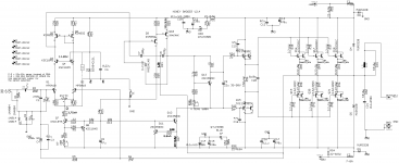
Akimet: I used the schematic of original HB. The layout I made on my own. I have routed the electrical lines different to the original HB layout. I took the different pinouts into account and double checked things like this many times.
Regards,
Oliver
Kay Pirinha:when I short circuit the "Input +" and "Input -" and switch on the amplifier, R50 is ice cold and also stays ice cold. So what does it mean and what to do next?
Akimet: I used the schematic of original HB. The layout I made on my own. I have routed the electrical lines different to the original HB layout. I took the different pinouts into account and double checked things like this many times.
Regards,
Oliver
if there is a sound quality difference with the input capacitor, can someone publish a test of say a 1uf / 16v ceramic ( tiny) vs 1uf / 600v poly or any other type driving a 47k ohm input impedance and a few volts max blocking. I have been unable to hear or visually see any difference not related to the exact value (+- 5%) of the capacitors themselves.
*1uf into 47k yeilds 3.4hz LPF
olllo, it is likely the pre output driver. pull out all the transistors on the R50 output and power on again.
*1uf into 47k yeilds 3.4hz LPF
olllo, it is likely the pre output driver. pull out all the transistors on the R50 output and power on again.
Last edited:
I would try removing the 15033,32 and replace with KSA1381 KSC3503. and test for oscillation. These transistors won't be able to drive to full power but may kill the oscillation ( output speed issue). R34,35 could go to 47 ohms. Your schematic appears to have 2 transistors in each of the driver and output positions where there should only be one.
Last edited:
Hi Olllo,
If the input is shorted and R50 remains cool it seems to me that your input might be picking up RF noise when the input is 'open' and amplifying it.
However it could also be PCB layout related with your output and input being so close together.
May I suggest that you test this by plugging in a normal signal source - eg a CD player turned on but nothing playing. The CD output is very low impedance, like an input short. If R50 remains cool it could be RF.
Now play a CD, preferably a quiet one. If R50 gets hot again you probably have an unintended feedback loop from output back to input.
There should be no load connected of course. I do not know how it would be fixed other than using the official PCB.
As I have two HB boards half-finished on my workbench at the moment, my two cents:
A long time ago I had a wildly oscillating 100W-Elrad-Amp. It took me quite a while to find that the resistors in the Boucherot circuit didn´t look like it, but were wire-wound and caused the problem. You used wire-wound resistors for R49 and R50, which I would try to replace with the 3W metal film types Reichelt offers (Part-ID: AKA RSMF3TB 10R0).
Not related to the actual problem: what I find missing is the thermal coupling of Q1 & Q2 as well as the common little heat sink for Q10, 11 and 12.
By the way, creating a "good" layout is a lot more than connecting dots correctly, so the best solution would be to change to the original layout ...
Last edited:
Hey,
Kay Pirinha:when I short circuit the "Input +" and "Input -" and switch on the amplifier, R50 is ice cold and also stays ice cold. So what does it mean and what to do next?
Hi Oliver,
well, this exactly confirms my suspicion! The input ist too close to the output, the output couples cpacitively into the input, hence causing oscillation, supposedly in the MHz range.
Just to exclude another possible reason, you might try to replace those six wire wound 0R22 emitter resistors by none-inductive ones. Please look at www.pollin.de, they might still offer these resistors, made by Futaba.
Best and definitive solution would surely be to replace the PCB's by official ones from the DIYAudio store.
Best regards!
im getting an itch to build another amp and this one may fit the bill. i have a few questions for starting off. not looking to do anything too fancy or off the wall with this build. most likely be pushing 8ohm speakers but would also like to be able to do 4ohms also.
is the universal power supply board in the store good enough for the honey badger with 2 channels?
also trying to read what transformer would i need. after skimming the first 120 pages or so the general understanding is a 600va-800va with a 35v-0-35v or 45v-0-45v outputs.
my history is that it's been a while but i have built 2 gain clone amps that work beautifully but more power may be needed eventually.
The DIYA supply PCB is more than adequate. 4R , go toward the lower end of Badger supply voltages (45-50V rails) , more SOA. Possibly Sanken outputs. I ran a dual VC paralleled sub with 3 pair of the big Sankens at +/- 43V. 2SA2151 |Sanken Electric Way better 3A+ DC SOA @ 40-50V , more Hfe ... better for the EF2 badger. I shy away from the ON semi products.
OS
OS
8200uf or 10,000..."Honey" and "Badger" sounds more like 6800uf's Lol. Still cluby and bubbly sounding....the bigger sizes will bring a cleared more fidelity sound...And Smoother Deeper bass and better speaker interaction.
It probably don't help I have garbo suspect 6800uf's in CapooCon or something or another...like Capxcon's junk lol
I got a great solution some China NOVAR LA audio Grade 50v 10,000uf fits the marked bigger spacing too 30X45mm.
It probably don't help I have garbo suspect 6800uf's in CapooCon or something or another...like Capxcon's junk lol
I got a great solution some China NOVAR LA audio Grade 50v 10,000uf fits the marked bigger spacing too 30X45mm.
another...like Capxcon's junk lol
I got a great solution some China ... 50v 10,000uf...
Be careful. I built a huge power supply using a many China 10 mF caps in parallel. Was a lot of work, took me ages. It worked well for a while, then the caps started bulging and transformed into something that I'd electrically describe as a resistor. I was lucky the smoke came out slowly.
Make sure to get no fake caps, get them from reliable sellers. It may cost a wee bit more, but the "extra costs" are nothing compared to the risk you're taking.

I did what I could with some stuff...Some blue caps guessing Polycarbonate or just monolithic Ceramic...got a be better than just plain old Ceramics...those are junk...
I do believe the TI TLO74 is a Buffer/Driver Input though..and had Ugly ceramics on it and surrounding...I did dump a few 104s and went up to .2 and .47 63-100v. about all I can do the power side went all the way up to a 2200uf 16v...might be slightly smoother and wider. Actually not that Bad of an opamp and is Low Noise version.
It's a No No for bad and the old like ceramics in the path in audio.....
I didn't spot any TL074's on my Honey Badger boards...I do believe the TI TLO74 is a Buffer/Driver Input though...

Best regards!
if you are running the VAS off of the main power supply, bigger caps will lower noise.
regulating the VAS supply voltage will work better but may require a voltage doubler or small transformer. This also delivers more power as the outputs come within 1.5v of the rails instead of 6v.
regulating the VAS supply voltage will work better but may require a voltage doubler or small transformer. This also delivers more power as the outputs come within 1.5v of the rails instead of 6v.
Last edited:
Well it's gonna be Mean Badger in a few days lol...sounds like i'm playing bass/guitar on a Receiver lol...bought some of yeah China looks well built Audio Grade NOVAR 50v 10,000uf...quite bulky a 30X45mm cans.
Has got to smooth out stuff and give a little more umphhh to the speakers. Like I said some junk filters in there I think and look cheap...but hey just a home Stereo Mostly or Clean PA.
Has got to smooth out stuff and give a little more umphhh to the speakers. Like I said some junk filters in there I think and look cheap...but hey just a home Stereo Mostly or Clean PA.
- Home
- Amplifiers
- Solid State
- diyAB Amp - The "Honey Badger"