... marketing dept wins, datasheet recommends for lowest overall THD.
As I said, stick to the datasheet if you want to do well in consumer reviews, don't if you want to experiment.
As I said, stick to the datasheet if you want to do well in consumer reviews, don't if you want to experiment.
Consumer reviews will always have a subjective aspect. Engineering dept WRT parts selection, not so much. And this was 30 years ago, chips with much better 'performance' are available today, yet 1541A can hold its own.
Perhaps the 'performance criteria' was based upon a second rate set of principles?.
Last edited:
As I said, stick to the datasheet if you want to do well in consumer reviews, don't if you want to experiment.
You clearly haven't given much thought to just how ridiculous a statement that is.
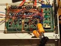
Well, in the mean time I've build another one, this time dual TDA1541A in simultaneous mode (fed from USB2I2S from JLSounds) with the 50Hz "ECDesign" mod. Still on active I/V waiting for the AD844 to arrive. Even now it sounds absolutely gorgeous.
Parallel or balanced?
Welcome to the simultaneous club, but balanced using transformers or a differential opamp etc is the next step.
I spend a few hours listening to mine yesterday (balanced with Sowter transformers) and I don't remember hearing the ringing of cymbals and the boing after the thud from Tympani & Bass drums, nor of how the player can subtly influence the sound of their trumpet depending on how they blow it.
In the past I've become used to the 'splash' sound of cymbals, the thud (only) of drums and well, a trumpet was a trumpet and could well have been synthesised.
My next step is battery power with LiFePo4 cells connected directly to the IC pins.
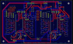
DUAL 1541 DAC BOARD V3 PARALLEL OR BALANCED
Attached is the first draft of my revised dual nos TDA1541 dac board.
Mods:
Moved regulators closer to the pcb edge for easier heatsinking,
Moved the -15v regulator to the other end of the dac closer to pin 15.
Moved all the dem caps closer to the pins.
Fitted a jumper to both dacs to select simultaneous or twc modes
Fitted UF.L pads for the digital signals for better quality connection to IanCs I2s-pcm board or others. (May delete the existing input pins and resistors)
Fitted pins for direct battery connection to each dacs power pins (each dac can have its own batteries or share them).
Fitted a jumper to link both pin 16s.
Opinions seem to differ on how to use the ground planes. Some seem to favour connecting every 0v pin to the planes at the component so there are no ground tracks as such.
Attachments
Actually it is run paralleled, so one TDA1541 for each channel with ADA4898 I/V and NJM2114 paralleld for HP output. I'll keep this build as it is for reference. Soundwise it's pretty good, immense soundstage, very good fine details and a an overall impression that it sounds just right. All listening tests with my AKG K702. The next build is on the way, this time balanced and with AD844 I/V and INA1620 as HP output.
Actually it is run paralleled, so one TDA1541 for each channel with ADA4898 I/V and NJM2114 paralleld for HP output. I'll keep this build as it is for reference. Soundwise it's pretty good, immense soundstage, very good fine details and a an overall impression that it sounds just right. All listening tests with my AKG K702. The next build is on the way, this time balanced and with AD844 I/V and INA1620 as HP output.
Let us know your views on parallel versus balanced.
My new pcb design can be stacked, with the lower board being a 'slave' and as I have a pair of spare TDA1541As, I will try parallel, balanced pairs. (or even two pairs of parallel)
I think those who are dismissive of the 1541 might change their mind if they listened to one of the recent implementations which are now possible thanks to the work of ECDesigns and IanCanada.
Hi All,
I'm just exploring nos dacs and read every thread I can find about them.
Lately I made a pcm56 based nos dac with 1kohm i/v resistor with 1nf cap paralel and using lm49990. I couldn't understand what does paralel cap doing?
What is the purpose of this capacitor? If I change value or type of this capacitor, what will happen?
I read datasheets for old pcm r2r dacs, none of them mention about these.
Also can I reduce i/v resistor further? Down to 470ohm? Is it better than 1k?
I'm just a rookie..
Btw")
I'm just exploring nos dacs and read every thread I can find about them.
Lately I made a pcm56 based nos dac with 1kohm i/v resistor with 1nf cap paralel and using lm49990. I couldn't understand what does paralel cap doing?
What is the purpose of this capacitor? If I change value or type of this capacitor, what will happen?
I read datasheets for old pcm r2r dacs, none of them mention about these.
Also can I reduce i/v resistor further? Down to 470ohm? Is it better than 1k?
I'm just a rookie..
Btw
Basically the cap "lowers" the gain for high frequencies. The value of that cap determines at which frequency the reduction starts. < f=1/2*pi*R*C >
From the equation we see that the resistor in combination with the cap dictates the frequency.
Also you can go lower with the resistor value but remember that this also requires the opamp to deliver more current (Ohms law, the voltage on the -Input of the opamp is 0V if you ground the +Input of the opamp).
The most significant result of lowering the resistor value is simply a lower output voltage.
Last edited:
Well, in the mean time I've build another one, this time dual TDA1541A in simultaneous mode (fed from USB2I2S from JLSounds) with the 50Hz "ECDesign" mod. Still on active I/V waiting for the AD844 to arrive. Even now it sounds absolutely gorgeous.
I like your inline layout of the dac chips, keeping the digital signal lines on the digital input side of the chips and the power supply lines on the supply pins side of the chips, allowing for short paths and small current loops, and avoiding mixing and intermingling the signal and power paths.
Basically the cap "lowers" the gain for high frequencies. The value of that cap determines at which frequency the reduction starts. < f=1/2*pi*R*C >
From the equation we see that the resistor in combination with the cap dictates the frequency.
Also you can go lower with the resistor value but remember that this also requires the opamp to deliver more current (Ohms law, the voltage on the -Input of the opamp is 0V if you ground the +Input of the opamp).
The most significant result of lowering the resistor value is simply a lower output voltage.
If I aim for 24khz cutoff and use 1k i/v resistor, I need to use 6.6nf cap. Is that right?
What cutoff frequency should I target? Right now 1k with 1nf gives 159khz!. Sounds horrible?
Also as you said, I grounded positive input of opamps..
Best overall TDA 1541A circuit
This is a question aimed at John at EC Designs, but anyone else can chip in.
This is a very long thread but if I were to sum up what seem to be the best design aspects to get maximum performance from the TDA1541A, it would be: Operate TDA 1541A in simultaneous mode, even better use 2 DACs per channel and operate in Signed Magnitude mode. Operate at 50hz DEM clock.
This leaves I/V conversion and I see in earlier designs (for example post 4489) John used a 115V Passive Current Source fed I/V stage using cascode BF862 FETs and 500 ohm I/V resistor. In the Signed Magnitude circuit, post 6116, the I/V is simply a 75R resistor with 1k1 resistor from the +5V line supplying the 4mA bias. Very simple versus relatively complex
My question: Assuming Signed Magnitude operation and 50Hz DEM clock, what is the best I/V circuit to use? The output will feed a headphone amplifier with 20dB closed loop gain.
My own current circuit is NOS TDA1541A with normal DEM clock, I2S mode and OPA 660 (Thosten Loesch) I/V converter circuit. It sounds pretty sweet to my ears but now I want to build what this thread is all about: The ULTIMATE NOS DAC with TDA1541A, and the only thing not finalised in my head is the I/V converter.
I suspect that the best solution for I/V will be subjective, conditioned with personal bias and subject to physical size and cost constraints.
I appreciate everyone has personal bias etc. However, it is enormously time consuming and in fact impossible to build each and every iteration then do comaprative listening tests to determine which is best. In a thread like this, which is many years old and dedicated to the TDA1541 (although I know the TDA1543 is also discussed), then people have already done a lot of this work (it is interesting to see how John at EC Designs has completely changed his implementation of the TDA1541 over the years as his knowledge - and listening tests guided his thoughts). My intention is to build maybe 3 different I/V configurations that I can add to an identical "front end" and see for myself which I prefer. But getting the choice down to 3 or 4 requires feedback from people who have spent time investigating this.
Well then. I think one of your considerations should be to use the current offset of the 1541A to bias a tube which sets up close to zero volt bias, something low noise and high mu, Rp 2k ish, 15mA ish, loaded with a 2:1 step down of considerable quality, 10 ohms in the cathode circuit, adjust grid leak/ IV resistor to suit system gain (context), something around 25 to 47 ohms.
I appreciate everyone has personal bias etc. However, it is enormously time consuming and in fact impossible to build each and every iteration then do comaprative listening tests to determine which is best. In a thread like this, which is many years old and dedicated to the TDA1541 (although I know the TDA1543 is also discussed), then people have already done a lot of this work (it is interesting to see how John at EC Designs has completely changed his implementation of the TDA1541 over the years as his knowledge - and listening tests guided his thoughts). My intention is to build maybe 3 different I/V configurations that I can add to an identical "front end" and see for myself which I prefer. But getting the choice down to 3 or 4 requires feedback from people who have spent time investigating this.
I recommend and use Sowter I/V transformers as are also used in very high end commercial Dacs. However this is undoubtedly because they are a very expensive option compared to a couple of opamps. (£266 per pair)
DAC I/V CONVERSION OUTPUT TRANSFORMERS
You can fine tune the sound by playing with the secondary load resistor and the value of the I/V resistor and whether you connect the primary and/or secondary in parallel or series.
I use two dacs in nos, balanced (simultaneous) mode so the transformer is the ideal solution and produces very clean audio with no need for further filtering. The step up ratio of 10:1 also means no further preamplification is needed.
There is no need to inject current to cancel the output offset as the primary is simply connected between the + & - outputs so no DC flows through the transformer.
Finally, there is complete galvanic isolation between the DAC and the power amp' volume control so no common mode noise.
So in my view, dual 1541s with IanCanada's I2S-pcm adaptor to drive them in balanced* nos sim mode, ECD's 50HZ dem clocking with Nichicon low leakage UKL series caps, and Sowter transformers is the ultimate 1541 nos dac. Possibly improved with LifePo4 battery power.
* Balanced rather than parallel is preferred because common mode digital noise will cancel in the bifilar wound transformer.
Last edited:
I recommend and use Sowter I/V transformers as are also used in very high end commercial Dacs. However this is undoubtedly because they are a very expensive option compared to a couple of opamps. (£266 per pair)
DAC I/V CONVERSION OUTPUT TRANSFORMERS
You can fine tune the sound by playing with the secondary load resistor and the value of the I/V resistor and whether you connect the primary and/or secondary in parallel or series.
I use two dacs in nos, balanced (simultaneous) mode so the transformer is the ideal solution and produces very clean audio with no need for further filtering. The step up ratio of 10:1 also means no further preamplification is needed.
There is no need to inject current to cancel the output offset as the primary is simply connected between the + & - outputs so no DC flows through the transformer.
Finally, there is complete galvanic isolation between the DAC and the power amp' volume control so no common mode noise.
So in my view, dual 1541s with IanCanada's I2S-pcm adaptor to drive them in balanced* nos sim mode, ECD's 50HZ dem clocking with Nichicon low leakage UKL series caps, and Sowter transformers is the ultimate 1541 nos dac. Possibly improved with LifePo4 battery power.
* Balanced rather than parallel is preferred because common mode digital noise will cancel in the bifilar wound transformer.
I can second batterymans observations on the Sowter transformers. They really shine when used with TDA1541 in NOS mode.
I also use TDA1541 in simultanious mode and with 50 Hz DEM, but up until now only in single ended mode. I am planning to use TDA1541 in balanced mode at a later time and with battery PS..
- Home
- Source & Line
- Digital Line Level
- Building the ultimate NOS DAC using TDA1541A