No, such a thing wouldn't be enough.
What kind of C/W value should I be looking at then?.
And thank you!
Temperature now in Greece is about 23°C.
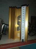
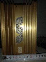
Mine jlh using this heatsink jump to 48°C after 10 minutes when the transistors body is 55°C.
Mine jlh using this heatsink jump to 48°C after 10 minutes when the transistors body is 55°C.
Attachments
Last edited:
What is the room temperature?
Denmark - Currently we have 22 degrees inside - can get hot in the summer, but that can be dealt with when that happens..
That's not too far off the 20x10x4 cm one I asked about. And I assume that 55 degree body temperature is acceptable?.Temperature now in Greece is about 23°C.
Mine jlh using this heatsink jump to 48°C after 10 minutes when the transistors body is 55°C.
You also have a regulator on yours which I assume is there for a reason.
No l haven't a regulator, just one more transistor that isn't connected.Denmark - Currently we have 22 degrees inside - can get hot in the summer, but that can be dealt with when that happens..
That's not too far off the 20x10x4 cm one I asked about. And I assume that 55 degree body temperature is acceptable?.
You also have a regulator on yours which I assume is there for a reason.
Transistor's case temperature isn't semiconductor's temperature!
Last edited:
No l haven't a regulator, just one more transistor that isn't connected.
Transistor's case temperature isn't semiconductor's temperature!
Clever ( :
And very well aware of that.
Any experience with this version of JLH 1969 amp? Mos fet output...
J554 P-MOS FET JLH1969 Class A Power amplifier kit (2 channel amp kit) | eBay
J554 P-MOS FET JLH1969 Class A Power amplifier kit (2 channel amp kit) | eBay
Hi Nigel
This 2.2k resistor is the one on the base-emitter junction of the lower output transistor?
You raise interesting questions on the JLH design and this is another. I have indeed considered this resistor, but after a "walk around the park" it is best left alone.
One of the problems discussed in this thread and elsewhere is that the speed of the output transistors limits the practical frequency response of the amplifier. A typical modern 2N3055 from ON semi has a gain cut-off frequency of about 50-60 kHz. That may or may not be a problem depending on the signal source material i.e. your preamp etc. To increase the speed of a transistor, more base current has to be supplied if it has to work beyond its fhfe, which means taking current out of the base (to turn it off) as much as putting current into it. I recall in Doug Self's WW article, he complained about the old 2N3055's drawing more current in a Class AB amp. at 30kHz - those old ones had an fhfe of only 10kHz. (What he did not say is that this could be addressed using 10 ohm base resistors instead of 100 ohms, but that would have meant increasing the driver current and dissipation etc).
So the point is that to increase the speed without a negative bias supply in the JLH, this base resistor should be lower. But there are consequences. A lower resistor shunts the base-emitter junction and reduces the open loop gain which is already rather low (about 600). But it will speed up the design.
As a rule of thumb the base resistor needs to take as much current out of the base as goes in if the overall current is not to increase at high frequencies. In a Class AB amp, a complementary driver arrangement can do that but not in the JLH,
If this resistor is reduced, the driver current has to increase. But that will lead to a thermal problem.
As the base-emitter junction voltage reduces with increasing temperature, a lower impedance source will allow more base current to flow into the transistor and so make the thermal stability worse - probably a lot worse. One of the points about the JLH is that by feeding essentially the output transistors with current, rather than voltage, the current gain change with temperature is less and the thermal stability higher than might have been expected without using emitter resistors etc.
So the rade-off which JLH made is to keep the resistor high, which does virtually nothing for improving speed, but keeps the low frequency open loop gain high and respectable, if not ideal, thermal stability.
To summarise, yes, the circuit would benefit from a lower resistor but that would create other problems.
Thanks John. My thoughts went in a similar direction. As some may have noticed I have been a bit unconvinced by some of the " better " tansistors and thought gain would be the factor more than vast hf. Doug Self calls some Super Beta types. From his graphs these not only do high gain into low resistance they are also higher gain. For our needs most transistors give their best gain wise when below 2 amps.
Empirically, imho you can get this resistor down to cca 1K2. Best values will possibly be in 1K5 - 1K8 range (plastic TIP3055/MJE2055). But note that I wasn't ever interested in 27V (or more) classic version, but a scaled down 15-18V version (for precision nearfield listening). This means lower value resistors in bootstrap section, and there may be a this scenarion-only connection!
Any experience with this version of JLH 1969 amp? Mos fet output...
J554 P-MOS FET JLH1969 Class A Power amplifier kit (2 channel amp kit) | eBay
I bought it and I got mad with the seller.
it's just a P version of a jlh69 with mosfet output and all that without any amenagement.
I have never assembled, I do not want to burn everything.
I have not tested the MOS but I have a big doubt when their origin ...
for information, it's the same seller who stole a schema to destroy X and put it on aliexpress and ebay ...
So, I'm not buying anything from him
Thank you!.
When I was traversing eBay yesterday, he was one of the sellers I was looking at, so this is definitely in the "nice to know" category!.
Question: You wrote "amenagement" - did you mean that seller didn't change the layout and just switched to fets and that's it?.
Question: You wrote "amenagement" - did you mean that seller didn't change the layout and just switched to fets and that's it?.
Yes thats exactly it .
no change from the BJT model
I can confirm, I have the same pcb in BJT sold by this guy
prasi's pcb are for 2003 jlh ,not for 69Now Prasi's pcb is here,tested!
Do not buy those unknown low quality ebay boards
Fake parts all over the ware!
Ha ha, i believe that Prasi can do it in minutesprasi's pcb are for 2003 jlh ,not for 69
")
Hi
I’ve built the 69 version and really enjoy it.
I’ve also build the Penultimate (dual polarity w ccs for front end and bias current)
For my taste I prefer the 69 version and recently discovered that a dual supply rails version has been implemented successfully.
Does anybody have some PCBs for the dual rail supply 69 version ? Schematic attached.
I just bought some Xtrm that would be perfect for 2 mono amp.
Note to self; finish MoFo first.
Thanks
Eric
Attachments
Last edited:
- Home
- Amplifiers
- Solid State
- JLH 10 Watt class A amplifier