Hi,
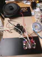
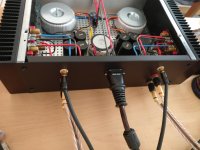
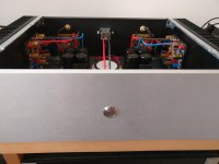
Here's my final build")
Just need to add a fuse and to connect the switch to the 12V to enlight it.
I tested it a few hours this week end, and i like it a lot. I'm not very good at describing the sound and english is not my first language, but i'll try.
My system is composed of a PC with Qobuz, an Atoll Dac100SE directly wired to the power amp, I don't have a preamp for the moment, and a pair of DIY speakers, the Prima from Justdiyit (Scanspeak discovery serie).
My previous amp was a 5 channels Emotiva UPA-5, that was already a lot better than my Denon X4000. But now I can hear that the Emotiva was not that good, the bass were not tight and not very defined. With the V4 everything feels very clear and transparent.
I can feel the the V4 is less powerfull than the Emotiva, which is supposed to be 5x125w/8ohm, but it's enough to drive the Prima and make my neighbours come to yell at me
And more importantly, the sound is still very clear at higher volume level !
Anyway, I'll will try to make the V4H later !! =D
I think that now, I've other thing to work on to improve my system (preamp, dac)
Fabio
Here's my final build
Just need to add a fuse and to connect the switch to the 12V to enlight it.
I tested it a few hours this week end, and i like it a lot. I'm not very good at describing the sound and english is not my first language, but i'll try.
My system is composed of a PC with Qobuz, an Atoll Dac100SE directly wired to the power amp, I don't have a preamp for the moment, and a pair of DIY speakers, the Prima from Justdiyit (Scanspeak discovery serie).
My previous amp was a 5 channels Emotiva UPA-5, that was already a lot better than my Denon X4000. But now I can hear that the Emotiva was not that good, the bass were not tight and not very defined. With the V4 everything feels very clear and transparent.
I can feel the the V4 is less powerfull than the Emotiva, which is supposed to be 5x125w/8ohm, but it's enough to drive the Prima and make my neighbours come to yell at me
And more importantly, the sound is still very clear at higher volume level !
Anyway, I'll will try to make the V4H later !! =D
I think that now, I've other thing to work on to improve my system (preamp, dac)
Fabio
Attachments
Thanks Loafimus,
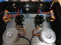
Protection boards are these ones :
Modules de protection stereo pour haut parleur 12V 16A (La paire) - Audiophonics
The only thing I didn't understand is, if they are only temporisation or DC sense as well =)
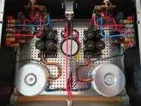
The transformers à 2x25V 160VA each, and the small one is a 2x12V 30VA for the protection boards.
Protection boards are these ones :
Modules de protection stereo pour haut parleur 12V 16A (La paire) - Audiophonics
The only thing I didn't understand is, if they are only temporisation or DC sense as well =)
The transformers à 2x25V 160VA each, and the small one is a 2x12V 30VA for the protection boards.
I found them on ebay too :
Assembled 10A speaker protection board suitable for BTL circuit CL-176 -HL | eBay
Assembled 10A speaker protection board suitable for BTL circuit CL-176 -HL | eBay
Hi,
Here's my final build
Just need to add a fuse and to connect the switch to the 12V to enlight it.
I tested it a few hours this week end, and i like it a lot. I'm not very good at describing the sound and english is not my first language, but i'll try.
My system is composed of a PC with Qobuz, an Atoll Dac100SE directly wired to the power amp, I don't have a preamp for the moment, and a pair of DIY speakers, the Prima from Justdiyit (Scanspeak discovery serie).
My previous amp was a 5 channels Emotiva UPA-5, that was already a lot better than my Denon X4000. But now I can hear that the Emotiva was not that good, the bass were not tight and not very defined. With the V4 everything feels very clear and transparent.
I can feel the the V4 is less powerfull than the Emotiva, which is supposed to be 5x125w/8ohm, but it's enough to drive the Prima and make my neighbours come to yell at me
And more importantly, the sound is still very clear at higher volume level !
Anyway, I'll will try to make the V4H later !! =D
I think that now, I've other thing to work on to improve my system (preamp, dac)
Fabio

Please confirm if it is a transconductance amplifier
Hi all and special Mr. Shaan,
It could confirm if it's even a current feedback amplifier. I know little but transconductance amplifiers usually have a sense resistor, from .33 to .50R, with 5 or 10W (KOA). Could confirm it's really transconductance amp as explained in the book "Loudspeaker operation: The superiority of current drive over voltage drive", by Esa Meriläinen. Thank you.
V4 sounds better in every way, from the lowest notes to the highest. Being a "current feedback" amplifier it is inherently very fast so kicks and crashes come alive. And everybody who has heard a PeeCeeBee commented how it loves the vocals and strings. V4 is neither too forward nor too laid-back. In my experience, a well balanced amplifier.
Hi all and special Mr. Shaan,
It could confirm if it's even a current feedback amplifier. I know little but transconductance amplifiers usually have a sense resistor, from .33 to .50R, with 5 or 10W (KOA). Could confirm it's really transconductance amp as explained in the book "Loudspeaker operation: The superiority of current drive over voltage drive", by Esa Meriläinen. Thank you.
Current amp
when did you use an expression ... Being a "current feedback" amplifier it is inherently very fast so kicks and crashes come alive ... in post #34. Just a simple matter: every voltage amplifier, even Lfet, can be transformed into transconductance. Maybe, for anyone who wants an experience! This recipe can be seen here FAQ about current-drive | Current-Drive - The Natural Way of Loudspeaker Operation. Thanks for the clarification.
Hi Augustoriodosul.
What makes you think it is a transconductance amp?
when did you use an expression ... Being a "current feedback" amplifier it is inherently very fast so kicks and crashes come alive ... in post #34. Just a simple matter: every voltage amplifier, even Lfet, can be transformed into transconductance. Maybe, for anyone who wants an experience! This recipe can be seen here FAQ about current-drive | Current-Drive - The Natural Way of Loudspeaker Operation. Thanks for the clarification.
Late V4 builder in need of troubleshooting help:
I've assembled both boards of V4 and completed Shaan's PSU too. Vcc and Vee are +36.2V and -36.15V, respectively, measured at the DC input points of one V4 board.
I followed the steps for power up, namely, switch on briefly for 1 sec and read the voltage reading between the leads of R29 or R30, check that both LEDs light up, check heat on 1R/2W resistor (I'm actually using 1.3R/5W), VR1 and 2 turned to max, VR3 turned to minimum, etc.
I'm unable to observe any voltage during the brief power on across R29/30. 1R/2W is cool, no heat.
Switched on again and started turning trimpots VR1 and VR2 but observed no voltage across R29/30, even when turning both to minimum.
Finally on checking the DC offset from the amp it shows -19.35V DC.
Any idea what could be wrong?
Checks done:
1/ Q1 and Q2 checked. They're both correct (BC556B and BC546B, resp).
2/ Q9 and Q10 checked for correct BJTs and orientation of pins and both found correct (KSE350 and KSE340, resp).
3/ Q11 and Q12 checked for pin orientation and found correct (K1058 and J162, resp).
4/ all electrolytics checked for polarity.
5/ all diodes checked for orientation.
Any pointers much appreciated.
Late V4 builder in need of troubleshooting help:
I've assembled both boards of V4 and completed Shaan's PSU too. Vcc and Vee are +36.2V and -36.15V, respectively, measured at the DC input points of one V4 board.
I followed the steps for power up, namely, switch on briefly for 1 sec and read the voltage reading between the leads of R29 or R30, check that both LEDs light up, check heat on 1R/2W resistor (I'm actually using 1.3R/5W), VR1 and 2 turned to max, VR3 turned to minimum, etc.
I'm unable to observe any voltage during the brief power on across R29/30. 1R/2W is cool, no heat.
Switched on again and started turning trimpots VR1 and VR2 but observed no voltage across R29/30, even when turning both to minimum.
Finally on checking the DC offset from the amp it shows -19.35V DC.
Any idea what could be wrong?
Checks done:
1/ Q1 and Q2 checked. They're both correct (BC556B and BC546B, resp).
2/ Q9 and Q10 checked for correct BJTs and orientation of pins and both found correct (KSE350 and KSE340, resp).
3/ Q11 and Q12 checked for pin orientation and found correct (K1058 and J162, resp).
4/ all electrolytics checked for polarity.
5/ all diodes checked for orientation.
Any pointers much appreciated.
I had exactly the issue, -20V on the output.
It turns out that I mistakely put 2 KSE350 on the board, so only one side was working.
Did you checked both R29 and R30 ?
I had exactly the issue, -20V on the output.
It turns out that I mistakely put 2 KSE350 on the board, so only one side was working.
Did you checked both R29 and R30 ?
Exactly the same mistake I did, Joshua check those out for the right markings
Replaced VR1 and 3 and observed the exact same thing as yesterday, namely, no voltage across R30 after powering up the V4 board, DC offset of > -19V.
I tested the removed VR1 and 3 and they're both working fine in isolation out of the board. Could measure extreme values 0R and ~500R and values in between. Something else is not right.
I also checked Q11 and 12 and they're the correct latFETs in the correct positions.
Any pointers?
To add: neither LED lights up when power is given to V4 board. Vcc/Vee are +35.9V/-36.15V.
Last edited:
To add: neither LED lights up when power is given to V4 board. Vcc/Vee are +35.9V/-36.15V.
Turned out I made the mistake of not insulating the screw that bolts the K1058 LatFET from the metal ring around the screw hole on the V4 board. This shorted the Drain of Q11/K1058 to the chassis, so the output from the Drain was directed to ground. This damaged LED, diode D1 in the Vcc rail and the 10R resistor in series with D1. Luckily no semiconductor was damaged.
The P-channel J162 was also mounted without insulation but surprisingly it didn't have any short to chassis from any of its pins. Just to be safer I insulated the J162 too.
Both boards powered up successfully. One board tuned/biased successfully. Second board to be done over the weekend. I'm dying to start listening to this amp.
Thank you Shaan for the constant guidance.
- Home
- Group Buys
- PeeCeeBee V4 GB!