it's somewhat tricky to measure that , indeed , and that is main reason why I didn't follow that test yet
in fact ..... it could be made inserting 50-100mR resistors in drains (so no altering current gain dramatically) , two channel scope across resistors (floating , of course) and whatnot , then some fun with additive , substractive and wide eyes on two channels independently
now I just need to buy second probe , I stepped on two , gave two , now I'm having just one and things are too frenzy to even remember ordering
one could think that asking that simple test from Papa is too much ?
....... I do not trust the Papa-SIT SPICE models without verification. .....
I forgot to say - PapapSit model is made by Mr.MR ...... I believe enough confirmed in vivo
though , as I'm always saying - I'm pretty much illiterate , regarding LTSpice tricks and tips
@ lhquam
Mike got a set of two SIT-1 from Nelson
Fun With PASS-SIT-1 | AudioMaker
and I suppose he measured these and made with his SIT modeler
SIT Modeler | AudioMaker
the data you have, so they are for sure the representation of at least one existing Pa SIT.
:--))
Mike got a set of two SIT-1 from Nelson
Fun With PASS-SIT-1 | AudioMaker
and I suppose he measured these and made with his SIT modeler
SIT Modeler | AudioMaker
the data you have, so they are for sure the representation of at least one existing Pa SIT.
:--))
I am also using the MR Papa-SIT SPICE models. It should be noted that they do not include temperature coefficient parameters, thus they will not help to simulate the bias drift with temperature. I am using the Cordell IRFP9240 model since the default model in the LTSpice library has an abnormally high lambda parameter.
Below is a simulation of a maximally simplifier DEFiSIT output stage at 1W, 4W, 9W, and 16W into an 8R load. Note that the PapaSIT drain current Ix(PapaSit ) waveform begins to become weird at 9W where the output stage is leaving class-A as shown in the IRFP9240 source current Is(P9240) waveform. This might be due to the IRFP9240 transconductance being too high as Papa suggested in a previous post. I will do some experiment with lower values of Kp in the IRFP9240 SPICE model.
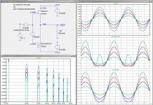
Below is a simulation of a maximally simplifier DEFiSIT output stage at 1W, 4W, 9W, and 16W into an 8R load. Note that the PapaSIT drain current Ix(PapaSit
) waveform begins to become weird at 9W where the output stage is leaving class-A as shown in the IRFP9240 source current Is(P9240) waveform. This might be due to the IRFP9240 transconductance being too high as Papa suggested in a previous post. I will do some experiment with lower values of Kp in the IRFP9240 SPICE model.Attachments
I'm still strongly convinced that sim is OK with that funny current distribution ;
I have simple logical explanation (it's always easy post hoc , isn't it ?) , but too lazy to type , demanding some subtle language battle with conundrum...... for which I'm not enough saturated with coffee right now
later maybe
I have simple logical explanation (it's always easy post hoc , isn't it ?) , but too lazy to type , demanding some subtle language battle with conundrum...... for which I'm not enough saturated with coffee right now
later maybe
this circuit is really demanding one to understand and even to simulate.
Sound is already fairly good, but my k2 is too high around 20dB over k3 so at 1W around
0.4% THD
Do you have any P channel MOSFETs with a lower transconductance to try. Alternatively, you can reduce the gm using a resistor divider R1 source to gate, and R2 drive to gate. R1/(R1+R2) will be the gm attenuation factor. This divider will also change the needed bias voltage for the IRFP9240.
....
Below is a simulation of a maximally simplifier DEFiSIT output stage at 1W, 4W, 9W, and 16W into an 8R load. ......
lhquam
observe currents through SIT source , mosfet source and through load
as I posted in #200
(with twice red in text .....
 )
)it is
red - current through 8R load
green - current through mosfet (IRFP9140)
blue - current through PapaSit
Do you have any P channel MOSFETs with a lower transconductance to try. Alternatively, you can reduce the gm using a resistor divider R1 source to gate, and R2 drive to gate. R1/(R1+R2) will be the gm attenuation factor. This divider will also change the needed bias voltage for the IRFP9240.
Yes Lhquam, I did this already....only in this way I could get the 1.5A.
Pa gave me the hint that this resistor network will load the autoformer with around 2mA. So you cannot go too deep with the R1 value.
He said that also the OS input stage impedance is affected. Hope I understood him right.
I will go to check my simulation again.
I am afraid at the moment only pa knows all aspects to match these parts to a working circuit.
I got some P channels with the lowest Vgs threshold the 9240 can show. I tested three vendors (always 20 parts) and only one had five with an Vgs that made it possible to get a match with my SK182 at 1A and 1.2A.
The sweet spot of the Pa Sits was shown by ZM at the beginning of the thread.
The TH-xx and SK might have a different sweet spot.
I intend to build a quick and dirty SIT-1 like circuit with the SK182 to find the point where the k2 is in a good relation to k3.
Maybe it helps to get the point with a Japanese DEFSIT.
What I do not understand here.....
In my simulation the P channel shows the distortion and the SIT curve is "good"
Also my SIT vurve is the big one and the P channel curve the smaller one,
All vice versa...
simple
your simulation is no good , you're using Mac , and with Mac , everything is opposite to PC
Yes Lhquam, I did this already....only in this way I could get the 1.5A.
Pa gave me the hint that this resistor network will load the autoformer with around 2mA. So you cannot go too deep with the R1 value.
He said that also the OS input stage impedance is affected. Hope I understood him right.
I will go to check my simulation again.
I am afraid at the moment only pa knows all aspects to match these parts to a working circuit.
Beast Builders post #1587 F4 Beast Builders shows formulas for the OS input impedance due to the resister divider.
What I do not understand here.....
In my simulation the P channel shows the distortion and the SIT curve is "good"
Also my SIT vurve is the big one and the P channel curve the smaller one,
All vice versa...
Could you show your simulation?
- Home
- Amplifiers
- Pass Labs
- Most Greedy Boy, of them all... or (there is no) DEFiSIT of Papa's Koans