None of the above.Do you apply some grinding process for making coating? Or do you rub it afterwards?
I buy, mix and spray paint.
I (like most people on this forum I guess) have no way of grinding and measure to micron level with pure graphite. I can only start to imagine what a mess that would make with all that black powder.
As I stated before the supplier gives me the numbers in a data sheet, I trust the numbers.
@wout31:
Don't know if this is relevant but found this manufacturer on Alibaba:
Factory Offer 99.95% Graphite Powder Nanoparticlea Or 1 Micron - Buy Graphite Powder,Nano Graphite Powder,Graphite Powder Factory Price Product on Alibaba.com
1 kg min. order
Cheers,
Jesper
Don't know if this is relevant but found this manufacturer on Alibaba:
Factory Offer 99.95% Graphite Powder Nanoparticlea Or 1 Micron - Buy Graphite Powder,Nano Graphite Powder,Graphite Powder Factory Price Product on Alibaba.com
1 kg min. order
Cheers,
Jesper
HI Jesper,@wout31:
Don't know if this is relevant but found this manufacturer on Alibaba:
Factory Offer 99.95% Graphite Powder Nanoparticlea Or 1 Micron - Buy Graphite Powder,Nano Graphite Powder,Graphite Powder Factory Price Product on Alibaba.com
1 kg min. order
Cheers,
Jesper
$ 200 - $ 1000 per kg + shipping + taxes.
Above my pay grade.
But thanks for looking this up. Maybe someday.
Last edited:
Hi again Jos ...
Actually I was thinking that maybe they would be interested in selling/supplying you with a small sample? Then it can be tried out and if it turns out fine I may/might be interested in joining in on a purchase (if ok with you, of course) - maybe others would as well?
When things are shipped from Asia in sample sizes shipping usually is not that high and at least here in Denmark we do not have taxes on samples.
An evening thought ...
Jesper
HI Jesper,
$ 200 - $ 1000 per kg + shipping + taxes.
Above my pay grade.
But thanks for looking this up. Maybe someday.
Actually I was thinking that maybe they would be interested in selling/supplying you with a small sample? Then it can be tried out and if it turns out fine I may/might be interested in joining in on a purchase (if ok with you, of course) - maybe others would as well?
When things are shipped from Asia in sample sizes shipping usually is not that high and at least here in Denmark we do not have taxes on samples.
An evening thought ...
Jesper
Last edited:
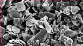
The particle nature of graphite may offer a potential model for increased charge density as per your observations of more dynamic sound and extended discharge time using your graphite coating. Your results seem to be replicated here Each graphite particle that adds surface irregularities could hold extra charge on the membrane compared to a nearly flat coating. Models that simplify the membrane to be a two dimensional surface will not model the three dimensional nature of the graphite particles. More experimentation is indicated with equipment that can estimate charge density as well as SPL levels with graphite particles of differing sizes eg 3microns versus 5 microns and single side versus two sided membrane coatings.
Attachments
Last edited:
Hillman Graphite Powdered Lubricant …...In the pic....less than $3. US...
Now I have post befor I am not into ...less say "reinventing the wheel"..
Diying a ESL panel With new Mylar....Look like fun....But I Like palying Sound thought these Panels...…looks.. yes I like good-great looking work others have done...But life ...for me is way to short....looks like most has been done...well that's Me!
When...the Quad...Sound lab... M Logan Panels ... older none working panels ..are just about a give away price...today....An are going to the junk yard....Not a lot of re-working of these panels...the quad only ones.
For years I been re-coating the Mylar on the ML panels....9"X 48"...12"X 46"...16"x 48"....an last year Move on to the CLS...22"X 48"...the Ezeys of the group to get open with out any rips in the Mylar....My big fear... I had for years...
But found a pair for $100. a panels to give it a shot....
There playing as I type this....only coating I have used is the one we all have in the home...Dawn's Dish Soap ….but others work as dose some shampoo...An adding in Some of this Graphite Powdered Lubricant
After reading in the 1980s Jim Strickland of Acoustat, Had tried ….used Prell shampoo on some panels
As panels coating..be for he went with ….Ampex Magnetic Tape cotaing…that looks-sounds.. like it may last for ever!
I gave the Soap a try....it work great...seeing how I Never would Glue the two sides of any panel togather….when thay all well need to be claned An recoated agine….for the great full output well all wont...get into the 90db at one watt...output ….so I can run these ML CLS panels with My old Dynaco ST70 like I am to day ….best sound I have ever had ...after 40 years of looking.....Paying...for all the speakers I could find.....Go fig.....Not bad look for 25 hours an $200.US
all just one mans finding
Attachments
![736511590265[1].jpg](/community/data/attachments/629/629743-33c2f9bb5c897cc489ac40c32c977c99.jpg)
Last edited:
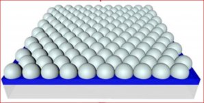
Possibly the ideal membrane coating structure would look like:
I am in the process of making graphene and nanotubes but it is for battery research and not ESL. Large sheets of graphene look like your ideal picture. However with current technology we cant produce such large sheets. Neither is this required imho. In case of graphene resistance will be quite low as well.
@kazap:
Hmmm... thinking aloud here: a large conductive surface area (the spheres) with low conductivity between the spheres.
Even smaller spheres would lead to even lower intermolecular surface area contact between the spheres presumably until the point where molecular surface "topology" is so uneven and coarse that contact between the spheres no longer is "structured" and the spheres' may no longer be considered to be spheres with a reduction in relative surface area gain when going to even lower sphere radii ...
Assuming that the above is not too far off ... Might it somehow help in structuring the particles in a sensible way to e.g. apply an electric field while the coating dries (DC/AC) ... Or a magnetic field of some kind? Could it force the particles to orient in a desired way?
Again - thinking aloud here ...
Cheers,
Jesper
Possibly the ideal membrane coating structure would look like:
Hmmm... thinking aloud here: a large conductive surface area (the spheres) with low conductivity between the spheres.
Even smaller spheres would lead to even lower intermolecular surface area contact between the spheres presumably until the point where molecular surface "topology" is so uneven and coarse that contact between the spheres no longer is "structured" and the spheres' may no longer be considered to be spheres with a reduction in relative surface area gain when going to even lower sphere radii ...
Assuming that the above is not too far off ... Might it somehow help in structuring the particles in a sensible way to e.g. apply an electric field while the coating dries (DC/AC) ... Or a magnetic field of some kind? Could it force the particles to orient in a desired way?
Again - thinking aloud here ...
Cheers,
Jesper
Cool, molecular physics, organic chemistry, advanced manufacturing. What else are we going to investigate without any yeild?
Since bifurcation was resolved into sincere confusion, I would refer to yet another diyer who's posted yet another recipe with some detergent in it. Only time will tell if the coating is long lasting.
However if you not living in Alaska then air humidity will be high enough for such topical coatings to conduct.
P.S. I do not believe that ESL coating is at such high demand which requires "inventors" to keep it secret in order to make huge amount of green staff.
Cheers
Thanks Kazap for this input. This could be an explanation of the weight being low in relation to the measured thickness. No pollution, no foaming, no compressing the coating with the thickness meter or other weird things, but a hemispherical surface. Never thought of that, but it might be thinking in the right direction. Thanks again.Possibly the ideal membrane coating structure would look like:
- About bigger particles: Found a supplier and will definitely try that.
- About double sided coating: There is no way I can think of how to accomplish that with the construction of the Quad ESL-63. Easier to first try the aforementioned option.
Seeing the word graphite being replace with graphene all of a sudden is something I do not understand. Maybe over 20 years, but not now, not for me, not for my wallet, not for my knowledge level, not for my skills, not as a DIY project.Large sheets of graphene look like your ideal picture. However with current technology we cant produce such large sheets.
Jesper, you're a creative thinker and I will note this one. Can't think of a way of how to make this work in the painting process as of yet, but hey it might be a good idea.apply an electric field while the coating dries (DC/AC) ... Or a magnetic field of some kind? Could it force the particles to orient in a desired way?
No huge demand required, I do this just for my own interest and fun. And a lot of fun it is. Even if I'll never find the prefect working solution or it fails after a few months, I still like what I'm doing in trying to figure this out. Not only the coating, but the whole Quad ESL-63 refurbishing project. So much to explore, so much to learn.I do not believe that ESL coating is at such high demand which requires "inventors" to keep it secret in order to make huge amount of green staff.
Cheers
Paints' binder is usually a polymer with density around water i.e. 1. Carbon, or graphite for this matter is about 2.1. Assuming very low C content you have to have 30% of trapped air at submicron level. That means you are one super lucky dude who accidentally created aforementioned thing or you're highly qualified material specialist who intentionally did it or measurements of yours are incorrect.
P.S. Rubbing graphite into mylar and then coating it with nylon is simple and reproducible coating if done right, however plane made out of s..t and sticks could not be utilized as a plane.
P.S. Rubbing graphite into mylar and then coating it with nylon is simple and reproducible coating if done right, however plane made out of s..t and sticks could not be utilized as a plane.
As I most definitely am not the latter, that only leaves the first option.That means you are one super lucky dude who accidentally created aforementioned thing or you're highly qualified material specialist who intentionally did it or measurements of yours are incorrect.
")
The measurements are most definitely correct. Maybe with a (little) tolerance of course, but the thickness is measured with earlier shown thickness meter and weighing is done with 0.001 gram accurate precision jewellery scale (not the $ 10,000 version). Have made hundreds of coatings over the past 2 years and the last months I can repeat the process with same outcome in resistivity, thickness, weight and tension over and over again.
Let me explain calibration and measurement checks again.
- I measure thickness of 2, 3, 6 and 12 micron Mylar. All 4 measure up to the specification with my thickness meter. Tolerance 0.7 micron (according to specifications of manufacturer)
- I take a evenly big square part of Mylar, put it on the scale and all 4 come up to the weight per m2 specified by the manufacturer. Tolerance of the scale is 12% (according to specifications of manufacturer)
- Resistance per square is measured with a meter that ranges to 200 G Ohm. I measure at voltage close as possible to the charge voltage. Measured square is 1x1 inch, very fine silver mesh strips. Measured at multiple location on the spayed coating. Resolution of the meter is 0.01 M ohm. Precision of the resistivity meter is ± 3% + 5 (again according to specification of the manufacturer)
- Tension of the Mylar is measured with an analogue and a digital tension gauge to check if coating influences Mylar tension because of chemical reaction (it does I think as tension changes, so I have to know the result after applying the coating). Accuracy here is 0.001N ± 5% on the digital version. Accuracy on the analogue version is my Fingerspitzengefühl.
No, my meters don't have calibration certificates, so yes they may be off by some percentage
Still no way to measure charge unfortunately
Last edited:
I know anti gravity paint tool exists, but anti gravity paint? Adaptive resistance? Sorry, but your replies always confuse me, because I have no clue at all what you're talking about. Probably way above my pay grade and intelligence. Sorry.Or it is an anti-gravity coating with adaptive resistance depending on the kind of esl you put it on
Paints' binder is usually a polymer with density around water i.e. 1. Carbon, or graphite for this matter is about 2.1. Assuming very low C content you have to have 30% of trapped air at submicron level. That means you are one super lucky dude who accidentally created aforementioned thing or you're highly qualified material specialist who intentionally did it or measurements of yours are incorrect.
P.S. Rubbing graphite into mylar and then coating it with nylon is simple and reproducible coating if done right, however plane made out of s..t and sticks could not be utilized as a plane.
According to a picture supplied by wout31, the coating is very black so there is probably no low C-content (or it should be very, very, thick). So it is even worse than calculated.
Particle size of the used graphite is 3 micron. A binder must be used as well. It is a mission impossible to paint a coating with 3 micron particles suspended in a binder and have a thickness equal to the size of the suspended particles itself. Somehow there is something wrong.
Resistance up to 10^12 Ohm with graphite particle suspended in a binder? Take a look at this: The electrical resistivity of graphite–ICP filler versus wt% graphite... | Download Scientific Diagram
- Home
- Loudspeakers
- Planars & Exotics
- ESL Diaphragm coating