Maybe they (blue Philips) are better for the output of switching power supplies, like a Panasonic FC?
At output of switching PS where frequency is very high and there is no problem with low impedance loading, I think low ESR cap will be suitable. I just checked the blue Philips and found out that they are in the same parameter as Oscon (not a low ESR nor low Vloss). May be that's why I couldn't differentiate when one channel is using Oscon and the other channel is using this Philips. I think I liked them in my amplifier bypass but now I will be more careful.
BTW, Panasonic FM is lower impedance than the FC.
Hi Jesper,
Thanks for your comments on the Kaisei (yes, that's it) - a better Gold Tone, eh - I'm using some GTs in this regulator here and I hadn't thought about their possible contribution to the overall sound - might stretch the budget and try a couple
Not sure sumotan about describing the treble of these KAs - I often like to add a polyester + resistor filter on some of the power supplies outputs to reduce some of the edge but with this KA, I'm finding it seems good enough in the top without any assistance - I'm running an Ayre QB-9 dac and it's pretty neutral so poor recording are a bit rough on the tops but surprisingly, I can wear some MP3 data stream okay on the same setup, go figure
As a bit of an aside (threadjacking?) I was listening to ryanj's evolving 1541A dac on the weekend and it has a similar forgiveness when playing average quality material - It's quite strange really
I'm a bit reticent about the old Roe caps as I'm not so keen on the bass - bit the same with some of the Mundorfs too, despite their general acceptance - might just me being 'picky' about very clean bass perhaps
I like the BHC midrange sound and then I tried the T & the Slitfoils and my wallet took a beating!
I have a love affair with 1 dac that many ppl have over look, its the good old CS4328 dac.
Whoa, I thought I'm the only one who know that chip

Aaaah good me into TDA 1541. Heard the Sabre not for me even when playing DSD
I only have the 1541. How far is it from 1541A (and probably the crowns)?
Hi johnego,
Depends on the circuit, but for tube equipment I try to use polypropylene or polystyrene. Various manufacturers work well, Kemet being one of them. For solid state I've been using Wurth capacitors and of course the other usual suspects.
What I don't use are the "audiophile approved" capacitors as many aren't as good as the ones I do use, and are greatly more expensive on top of that. I also don't use "Ebay specials". That's just asking for trouble.
Many times it is how a capacitor is installed that determines how long it will last. Splay the leads and you either break the rubber seal or weaken it. I see this all the time.
-Chris
Because Im a compulsive tweaker Johnego.
Only BG N works well in Super E config for signal coupling, the rest of the caps don’t do well including bipolars. There’s a bipolar cap that does fanatstic as signal coupling & dare I say even better than foil caps like Mundorf Supreme but its my little secret
Can you share that secret with us?
BTW, Panasonic FM is lower impedance than the FC.
That’s true, never claimed they were, should have been more clear. I just don’t think audio is where they were intended to be used.
I have a pile of them that have come from various boards, maybe I can make a sculpture out of them like people do with wine corks.
You mean the sound difference between Sabre & Tda 1541 Johnego ?
Different presentation, TDA in nos sounds more analog & yes Crown sounds way better then stock TDAs. Im using S1 on my dac. The other thing about the Tda, it got bass that I’ve never heard from other dac. First time I heard it was 20 yrs ago & it had stayed in my head hence the reason for playing with this old timer.
Different presentation, TDA in nos sounds more analog & yes Crown sounds way better then stock TDAs. Im using S1 on my dac. The other thing about the Tda, it got bass that I’ve never heard from other dac. First time I heard it was 20 yrs ago & it had stayed in my head hence the reason for playing with this old timer.
That's a nice machine if I'm seeing (Google images) the right one.So far, my HP 4263A LCR meter has done a great job of sorting out capacitors. It will also indicate ESR (impedance) at various frequencies. The impedance reading isn't that helpful to be honest, but the dissipation readings correlate with what I'm hearing a lot better than anything else so far.
Interesting the use of this brand, I think it's the first time I see it being mentioned in a forum.Hi johnego,
Depends on the circuit, but for tube equipment I try to use polypropylene or polystyrene. Various manufacturers work well, Kemet being one of them. For solid state I've been using Wurth capacitors and of course the other usual suspects.
Some are still available, under Vishay. I can buy a few in a shop here close buy, but values here available are pretty limited (1uF and 47uF, only)I have these good sounding Philips caps (mostly for decoupling, but feedback is ok too) in my inventory. Could anyone review it's sound?
https://www.vishay.com/docs/28316/116rll.pdf
Lots of mentions of Cyril Bateman's work. I studied his Capacitor Sounds series for a while and learned the following "rules":
...........
1. Capacitor distortion does not correlate with dissipation factor or ESR, but rather with dielectric absorption. Bateman's tests suggest that dielectric absorption is in fact the main cause of capacitor distortion.
2. Capacitors have an "optimum bias" level. THD is higher below this level, and above it. According to Bateman, "Optimum bias for most conventional 25 volt polar electrolytics was between 1 volt and 4 volts DC, while for 50 - 63 volt rated capacitors, optimum bias ranged from less than 2 volts to some 7 volts DC" (Capacitor Sounds 5, pg. 10). Note that "optimum bias" indicates lowest possible THD without regard for harmonic profile.
3. Once above this "optimum" bias, capacitor's H2 distortion ( and only H2) increases with DC bias voltage. An electrolytic cap biased at 50% of its voltage rating produces 6 times more THD than the same cap biased at just 10% of its rating, owing almost entirely to increased H2. For one electrolytic, a very low bias (below 10% of rating), minimized H2 to the point that H3 dominated the harmonic profile (yuck!). With bias at 20% of the voltage rating, H2 rose to equal H3, and and at all higher bias voltages beyond 20% of the rating, H2 dominated.
4. Both H2 and H3 distortions increase with AC signal voltage. Bateman warms: "[w]hen third harmonic distortion exceeds some 0.0003% of the test signal, intermodulation distortions become visible above the measurement noise floor. Any increase in AC signal results in much increased intermodulation and harmonic distortions" (Capacitor Sounds 5, pg. 11).
5. Bi-polar electrolytic caps distort half as much as their polar counterparts, and have less dielectric absorption too. Too bad they're big!
6. A film bypass with with an electrolytic cap can reduce distortion--larger bypasses more effectively so. A bypass with a capacitance of 10% of the main electrolytic proved marginally effective at reducing distortion, while a bypass with just 1% of the main cap's value yielded an insignificant reduction.
7. Film caps distort far less than electrolytics. A PET cap distorts 1/6 as much an optimally-biased polar electrolytic cap of the same capacitance, and 1/3 as much as a bi-polar electrolytic cap.
8. Polypropylene film caps distort less than polyesters. An unbiased WIMA MKS metallised PET cap distorted 2x as much as a WIMA FKP foil/PP cap and introduced significant IMD to the signal. When biased at 18v, the MKS distorted 28x as much as the FKP cap!
9. Foil/film caps distort less than metallised film caps. The #7 comparison isn't quite fair. Even polyester performs decently with a foil electrode. The WIMA FKS foil/PET series measured "almost as good" as WIMA FKP2 (Bateman's words in quotes, no direct comparisons were published). Hooray for foil.
10. COG ceramic disc caps distort thousands of times less than X7R ceramics. Bateman's XR7 cap test produced the scariest FFT I've ever seen! THD of .48%, 8000 times the distortion of the COG ceramic cap.
11. Other excellent dielectric options exist. Polycarbonate and polystyrene caps have very low distortion but are hard to find. Polyphenylene Sulphide caps are worth consideration: with a footprint only slightly larger than metallised PET, PPS caps distort almost as little as polypropylene caps.
......................................
So here is a graph that illustrates point #4 for electrolytic caps. (Pardon me...I flexed my primitive Excel skills to create this) There are some obvious gaps in Bateman's measurements, but certainly enough to establish a clear trend.
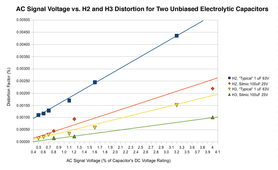
I converted the distortion measurements from Bateman's FFTs (in -dB) into distortion factor values (in %). I also expressed his AC voltages as % of cap's DC rating (instead of simply the actual voltage as Bateman used in his graphs), to make the comparison between different caps possible. I am very pleased that graphing in this way reveals a nearly linear correlation between AC signal voltage (as percent of cap rating) and distortion. It shouldn't be too hard to just extend the trajectory of the best-fit lines for prediction purposes.
Below is DC Bias vs. Distortion with a 0.3V Signal. Such big gaps in the data are infuriating, but hey, the lines sure fit well this way lol! This relationship is somewhat clearly quadratic. Note how H3 (two flat lines at the bottom) is unaffected by bias voltage. The left axis of the graph is mislabeled, as I chose last minute to include H3 just to prove point #3 from above.
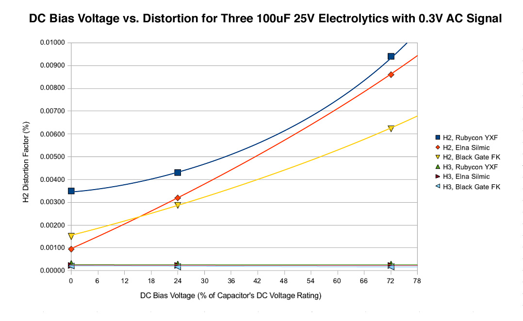
If I was better at math and/or had more data points (and a longer attention span), I would have figured out an equation to crudely predict electrolytic capacitor distortion by now. I suspect with this in hand, one could just plug in a cap's DC voltage rating, DC bias voltage and AC signal voltage and it would spit out a ballpark estimate. Fun
...........
1. Capacitor distortion does not correlate with dissipation factor or ESR, but rather with dielectric absorption. Bateman's tests suggest that dielectric absorption is in fact the main cause of capacitor distortion.
2. Capacitors have an "optimum bias" level. THD is higher below this level, and above it. According to Bateman, "Optimum bias for most conventional 25 volt polar electrolytics was between 1 volt and 4 volts DC, while for 50 - 63 volt rated capacitors, optimum bias ranged from less than 2 volts to some 7 volts DC" (Capacitor Sounds 5, pg. 10). Note that "optimum bias" indicates lowest possible THD without regard for harmonic profile.
3. Once above this "optimum" bias, capacitor's H2 distortion ( and only H2) increases with DC bias voltage. An electrolytic cap biased at 50% of its voltage rating produces 6 times more THD than the same cap biased at just 10% of its rating, owing almost entirely to increased H2. For one electrolytic, a very low bias (below 10% of rating), minimized H2 to the point that H3 dominated the harmonic profile (yuck!). With bias at 20% of the voltage rating, H2 rose to equal H3, and and at all higher bias voltages beyond 20% of the rating, H2 dominated.
4. Both H2 and H3 distortions increase with AC signal voltage. Bateman warms: "[w]hen third harmonic distortion exceeds some 0.0003% of the test signal, intermodulation distortions become visible above the measurement noise floor. Any increase in AC signal results in much increased intermodulation and harmonic distortions" (Capacitor Sounds 5, pg. 11).
5. Bi-polar electrolytic caps distort half as much as their polar counterparts, and have less dielectric absorption too. Too bad they're big!
6. A film bypass with with an electrolytic cap can reduce distortion--larger bypasses more effectively so. A bypass with a capacitance of 10% of the main electrolytic proved marginally effective at reducing distortion, while a bypass with just 1% of the main cap's value yielded an insignificant reduction.
7. Film caps distort far less than electrolytics. A PET cap distorts 1/6 as much an optimally-biased polar electrolytic cap of the same capacitance, and 1/3 as much as a bi-polar electrolytic cap.
8. Polypropylene film caps distort less than polyesters. An unbiased WIMA MKS metallised PET cap distorted 2x as much as a WIMA FKP foil/PP cap and introduced significant IMD to the signal. When biased at 18v, the MKS distorted 28x as much as the FKP cap!
9. Foil/film caps distort less than metallised film caps. The #7 comparison isn't quite fair. Even polyester performs decently with a foil electrode. The WIMA FKS foil/PET series measured "almost as good" as WIMA FKP2 (Bateman's words in quotes, no direct comparisons were published). Hooray for foil.
10. COG ceramic disc caps distort thousands of times less than X7R ceramics. Bateman's XR7 cap test produced the scariest FFT I've ever seen! THD of .48%, 8000 times the distortion of the COG ceramic cap.
11. Other excellent dielectric options exist. Polycarbonate and polystyrene caps have very low distortion but are hard to find. Polyphenylene Sulphide caps are worth consideration: with a footprint only slightly larger than metallised PET, PPS caps distort almost as little as polypropylene caps.
......................................
So here is a graph that illustrates point #4 for electrolytic caps. (Pardon me...I flexed my primitive Excel skills to create this) There are some obvious gaps in Bateman's measurements, but certainly enough to establish a clear trend.
I converted the distortion measurements from Bateman's FFTs (in -dB) into distortion factor values (in %). I also expressed his AC voltages as % of cap's DC rating (instead of simply the actual voltage as Bateman used in his graphs), to make the comparison between different caps possible. I am very pleased that graphing in this way reveals a nearly linear correlation between AC signal voltage (as percent of cap rating) and distortion. It shouldn't be too hard to just extend the trajectory of the best-fit lines for prediction purposes.
Below is DC Bias vs. Distortion with a 0.3V Signal. Such big gaps in the data are infuriating, but hey, the lines sure fit well this way lol! This relationship is somewhat clearly quadratic. Note how H3 (two flat lines at the bottom) is unaffected by bias voltage. The left axis of the graph is mislabeled, as I chose last minute to include H3 just to prove point #3 from above.
If I was better at math and/or had more data points (and a longer attention span), I would have figured out an equation to crudely predict electrolytic capacitor distortion by now. I suspect with this in hand, one could just plug in a cap's DC voltage rating, DC bias voltage and AC signal voltage and it would spit out a ballpark estimate. Fun
Last edited:
Hi Karl,
You're probably looking at the right screen. I bought it brand new and was giddy with excitement when it arrived. It's a wonderful piece of equipment if used properly. It's probably 20 years old now and has paid for itself many times over. These days you can buy one for a fraction of what I paid. At the same time I also bought an HP 34401A DVM which is still working great and has never been out of tolerance! I also got a new Philips PM-3070 oscilloscope. I had to rebuild the power supply and it works fine. It has had a lot of warranty repairs due to one small circuit board. Surface mount parts and it runs too darned hot. But the trace is sharper than the Tektronix products.
Good equipment will last a very long time, and usually pays for itself many times over. I wish I could afford to run out and buy today's current Keysight equipment!
Capacitors.
The build quality and dielectric are the important factors. A good industrial capacitor will usually outperform an audiophile brand rather easily. Industrial demands are far greater than home audio demands will ever be. These parts are used in far greater quantities than the audio market could ever use. Therefore the processes used to create these parts are under far better control. Consistency and reliability are two benefits of tighter control. That and the uses the parts are found in have far greater impact for a part failure than audio components. So reliability is a prime concern. As far as losses and distortion is concerned, those same factors are also important in industrial products. They just don't listen to the products as a rule. In addition, temperatures in industrial applications are typically much higher than in home equipment. With high temperatures, all characteristics are degraded in just about any component type you can think of. Therefore, they have to be just that much more reliable.
How to find these better parts? Get a good piece of test equipment so you can test samples. Then buy the types that measure well. Failing that, read the data sheets on these parts and learn how to decode what they are saying. That requires time and effort to educate yourselves. Of course a combination of test equipment, data sheets and 40 years of experience helps enormously.
-Chris
Hi stellarelephant,
All studies into anything needs interpretation. Dissipation factor is very similar to dielectric absorption. Over the short term each represents energy lost from the signal into the dielectric of the capacitor. That means distortion no matter how you want to slice it.
You should look at the entire body of work from many people in the field instead of just one author.
-Chris
Lots of mentions of Cyril Bateman's work. I studied his Capacitor Sounds series for a while and learned the following "rules":
2. Capacitors have an "optimum bias" level. THD is higher below this level, and above it. According to Bateman, "Optimum bias for most conventional 25 volt polar electrolytics was between 1 volt and 4 volts DC, while for 50 - 63 volt rated capacitors, optimum bias ranged from less than 2 volts to some 7 volts DC" (Capacitor Sounds 5, pg. 10). Note that "optimum bias" indicates lowest possible THD without regard for harmonic profile.
3. Once above this "optimum" bias, capacitor's H2 distortion ( and only H2) increases with DC bias voltage. An electrolytic cap biased at 50% of its voltage rating produces 6 times more THD than the same cap biased at just 10% of its rating, owing almost entirely to increased H2. For one electrolytic, a very low bias (below 10% of rating), minimized H2 to the point that H3 dominated the harmonic profile (yuck!). With bias at 20% of the voltage rating, H2 rose to equal H3, and and at all higher bias voltages beyond 20% of the rating, H2 dominated.
Nice work tweezering out Bateman's data! I'll agree that capacitor distortion seems to be proportional to level as well, but I will add one observation related to points 2 and 3 that is important to keep in mind.
When measuring distortion, you can never separate the analyzer distortion from the DUT distortion. You can only hope that your DUT is significantly dirtier than the analyzer, so that the numbers you obtain are reliable, affected only slightly by the analyzer residual
The reason for this is that the analyzer residual adds to the DUT residual, and that sum is what you see in the results. However, a harmonic of the DUT, especially one related to an asymmetric process such as one that would cause 2nd harmonic, may not combine additively with the 2nd harmonic of the analyzer. If the DUT's 2nd harmonic is the opposite polarity compared to the analyzer's 2nd harmonic, then as DUT 2nd harmonic rises to the level of the analyzer's 2nd harmonic residual, the sum will reach a null point, and then increase above this level, as DUT distortion rises and the analyzer's contribution to the sum becomes less significant.
So, in a test where you expect DUT distortion to rise with level, the analyzer and DUT distortion sum can appear to dip with increasing level and then get larger again as DUT drive continues to increase, as the sum goes through a cancellation region, solely because the analyzer has a non-zero residual.
This means that the observed "bias null" may be purely an illusion caused by the residual distortion level of the analyzer and the inevitable summing of the analyzer and DUT distortion, and that a different analyzer residual will place the observed "null" at a different DUT drive level, only because of this summation-cancellation phenomenon.
Taking this phenomenon another way, one can use this characteristic to dig deeper into the analyzer residual, since the point where the DUT and the analyzer cancels, the DUT and the analyzer have probably close to the same magnitude, but only if the DUT and analyzer harmonics are simply related, e.g. opposite polarity (180 degrees). I haven't dug deep enough into Taylor's series to know what restrictions there are on the harmonic decomposition of a monotonic transfer function, one that comes from a real, causal, circuit like an amplifier or component, but there may be some rules? If you can't nail this harmonic 'phase' down to 180 degrees or 0 degrees, then all bets are off, but it's an interesting idea.
At any rate, whenever you see a dip and a subsequent boost like that, you have found your analyzer residual, not necessarily "real" DUT behavior, because your analyzer always has some sort of a residual level.
Please forgive my ignorance on what is probably an obvious question that I don't seem to understand: what is the capacitor bias voltage and how we get to the optimum level?
On Batemans's sum up (very useful) he stated: "Optimum bias for most conventional 25 volt polar electrolytics was between 1 volt and 4 volts DC, while for 50 - 63 volt rated capacitors, optimum bias ranged from less than 2 volts to some 7 volts DC".
The capacitor would be used for what? Power supply bypass? Interstage coupling?
In the first case it sounds illogical to power (bias?) a capacitor with 5v, on say a 5 volt supply using a 25v capacitor or even a 63v capacitor. What about larger higher voltages?
In interstage coupling, DC voltage can be just a few millivolts.
What is it I am not getting?
Except if we are talking using two polar capacitor in series, and you are biasing the central point with 1 to 7 volts. That would be biasing for me. But how does that apply to power supplies?
The cap's bias voltage is more simply just the DC voltage that you can measure across the capacitor terminals. The bias will likely be determined by the to optimize behavior of other components. So you can optimize caps by measuring this voltage and choosing a cap that has the proper rating (IMO You may find more of a "sweet spot" than CB's "optimal" recommendation for lowest absolute THD by aiming for a natural H2/H3 harmonic profile...so maybe instead of a 10:1 ratio for rating vs. bias, something like 3:1 or 4:1?)
- Home
- Design & Build
- Parts
- Best electrolytic capacitors