Well, after a couple of weeks of see-sawing, drilling, sanding, gluing, etc. I think I have the case ready for the Amp!!!
Now I need to train in soldering and actually build the PCBs!
But all in all, I have two thoughts right now:
I have lost count of how much this case cost, but given that you need to purchase everything, the costs go up exponentially. For instance, I bought Aluminum not for a single case, I could have made 5, but I have to pay for the full sheet nonetheless. Same goes for drill bits... even if you need a single 3/8" hole, you have to pay $5 for that single bit. So unless you do this for a living or really, really want to make the chassis your own, purchasing from the store is much less expensive, much better finished, and frees up time to actually build the amps! ")
With that out of the way, here's the process to my 90% finished chassis.
Here's the first day, just assembling the pieces with masking tape to make sure everything fits:

Drilling L profiles to allow proper assembly. Bending would have saved a lot of time, but I don't have the machine to bend 2mm aluminum, so I designed it that every piece was flat. Perhaps not the best idea, maybe taking the pieces to be bent would have been a more clever approach:

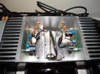
Here's the fantastic suggestion made here at the forum to allowing for the MOSFETs to be attached to the heatsink without the need for cables and other complex solutions. Thanks!!!

I decided to rivet some of the L profiles... this results in a side that looks like a showcasing of all the different types of bolts and rivets one can find. Not really happy with that, I may end up just replacing those with hex bolts as well:

To avoid bolts on the top and front sheets, I went for gluing the profiles to those sections. That was a really life saving decision, as perfect matching of the holes would have been a headache. This way, there is one section with holes, the other is just 'hand positioned' and then glued to the Ls. Now everything matches and is a bliss to assemble. Really happy with that decision:

Here's how the PCBs are positioned:


The case mostly in its final form, missing just the glass window with the name and logos:

Here's the back layout... I'm, for the time being, considering a front switch... still that is on the fence right now. We'll see:

This would be his definitive 'listening' location... much nicer with the wood and wall than on the glass dinner table

Thanks a lot for all the input I received, it really helped make everything clear. Of course, I have bothered my dad (who has been an electrical engineer all his life) with thousands of calls and questions, using his equipment when mine is lacking, or just when I need to vent frustration because I have no idea what I'm doing, so he has been a savior. Also, my wife has been incredibly supportive of me having the house upside down and living with aluminum shrapnel and drilling noise for all this time.
Thanks again! Now, onto the actual AMP!
Best regards,
Rafa.
Now I need to train in soldering and actually build the PCBs!
But all in all, I have two thoughts right now:
- I'm very happy with a full DIY chasis of my own design in which every single thing was done by hand (with machines, obviously!)
- I think the DIY Store Chassis are, without a doubt, the way to go and really inexpensive considering what they provide
I have lost count of how much this case cost, but given that you need to purchase everything, the costs go up exponentially. For instance, I bought Aluminum not for a single case, I could have made 5, but I have to pay for the full sheet nonetheless. Same goes for drill bits... even if you need a single 3/8" hole, you have to pay $5 for that single bit. So unless you do this for a living or really, really want to make the chassis your own, purchasing from the store is much less expensive, much better finished, and frees up time to actually build the amps!
With that out of the way, here's the process to my 90% finished chassis.
Here's the first day, just assembling the pieces with masking tape to make sure everything fits:
Drilling L profiles to allow proper assembly. Bending would have saved a lot of time, but I don't have the machine to bend 2mm aluminum, so I designed it that every piece was flat. Perhaps not the best idea, maybe taking the pieces to be bent would have been a more clever approach:
Here's the fantastic suggestion made here at the forum to allowing for the MOSFETs to be attached to the heatsink without the need for cables and other complex solutions. Thanks!!!
I decided to rivet some of the L profiles... this results in a side that looks like a showcasing of all the different types of bolts and rivets one can find. Not really happy with that, I may end up just replacing those with hex bolts as well:
To avoid bolts on the top and front sheets, I went for gluing the profiles to those sections. That was a really life saving decision, as perfect matching of the holes would have been a headache. This way, there is one section with holes, the other is just 'hand positioned' and then glued to the Ls. Now everything matches and is a bliss to assemble. Really happy with that decision:
Here's how the PCBs are positioned:
The case mostly in its final form, missing just the glass window with the name and logos:
Here's the back layout... I'm, for the time being, considering a front switch... still that is on the fence right now. We'll see:
This would be his definitive 'listening' location... much nicer with the wood and wall than on the glass dinner table
Thanks a lot for all the input I received, it really helped make everything clear. Of course, I have bothered my dad (who has been an electrical engineer all his life) with thousands of calls and questions, using his equipment when mine is lacking, or just when I need to vent frustration because I have no idea what I'm doing, so he has been a savior. Also, my wife has been incredibly supportive of me having the house upside down and living with aluminum shrapnel and drilling noise for all this time.
Thanks again! Now, onto the actual AMP!
Best regards,
Rafa.
Thanks 6L6! To you, I owe everything here... this is probably more 'your' AMP than it is mine, so thanks truly!!!
Thanks Alan and Dennis.
@Alan, I bought anodized Aluminum, so they have been with those 'plastic' protections up until two days ago. I just very gently rubbed them with WD40 and they get nice and shiny. Maybe this is not showing in the pictures properly. When I'm completely done, I'll disassemble all the case and give the exposed 'edges' a final sanding so they are nice and smooth, as well as with 'congruent' reflections (not sure how to explain this).
The inner parts that have been annotated in, I'll sand with a 400 water paper sand, and that'll be all. Assemble back together and that's it.
I'm still debating if covering the back panel with black vinyl (or paint?) to give the recessed panel (and the fact that it is holding the connectors) a different 'visual language', but that is also not yet clear at this point.
Any suggestions regarding the finishing of the surfaces? Was there any particular idea in mind behind your question?
Thanks again,
Rafa.
Well, after a couple of weeks of see-sawing, drilling, sanding, gluing, etc. I think I have the case ready for the Amp!!!
Nice!
Thanks for all the kind words friends! It certainly has been an interesting challenge.
Now that I am beginning to plan for the actual AMP side of building, I was wondering if I can fire away some questions? As I mentioned my dad is an electronics engineer, and has some doubts about some of the back panel connections.
Basically the core of the questions is: Why is there need for that 'common ground' in the form of the bare copper wire to the back?
He says his intuition would get rid of that common wire and do as follows:
He also says that he would use a shielded cable for the RCA connectors to the boards instead of electrical wire.
So, I'm a bit confused, and not know enough to validate my dad's suggestions or disproof them. So I am turning to you fellows with all your knowledge so that I can understand what is the science behind those decisions and why would it be better or worse to go the route that my dad proposes.
Thanks a lot!!! Best regards,
Rafa.
PS. I know I sound like a little boy, but I'm actually 40 It's just that I have 0 background in electronics, only the ears of a person that enjoys great music and this love for doing stuff myself... so I, as I research and learn about this new skill, I rely on the people that know of those subjects much more than I.
Now that I am beginning to plan for the actual AMP side of building, I was wondering if I can fire away some questions? As I mentioned my dad is an electronics engineer, and has some doubts about some of the back panel connections.
Basically the core of the questions is: Why is there need for that 'common ground' in the form of the bare copper wire to the back?
He says his intuition would get rid of that common wire and do as follows:
- Connect the boards GND to the PSU GND (as they are on the Build Guide 1.5)
- Leave the Speakers OUT + (the one that is just ground) only soldered to the Boards and NOT to that common ground (probably to avoid ground loops?)
He also says that he would use a shielded cable for the RCA connectors to the boards instead of electrical wire.
So, I'm a bit confused, and not know enough to validate my dad's suggestions or disproof them. So I am turning to you fellows with all your knowledge so that I can understand what is the science behind those decisions and why would it be better or worse to go the route that my dad proposes.
Thanks a lot!!! Best regards,
Rafa.
PS. I know I sound like a little boy, but I'm actually 40
It's just that I have 0 background in electronics, only the ears of a person that enjoys great music and this love for doing stuff myself... so I, as I research and learn about this new skill, I rely on the people that know of those subjects much more than I.
Last edited:
As I see it, no signal ground / Ground (earth, or whatever it's called in your area) connection conflict as the SMPS if fully isolated.
Coax for the signal if it makes you fell better. Your (Dad's) ground connection looks fine as well.
I think 6L6 just suggest to do so, not really a dogma (at least not to me, and I DO appreciate his build guides a lot).
Anyway, Dad's are (almost) always right .
Coax for the signal if it makes you fell better. Your (Dad's) ground connection looks fine as well.
I think 6L6 just suggest to do so, not really a dogma (at least not to me, and I DO appreciate his build guides a lot).
Anyway, Dad's are (almost) always right .
Last edited:
I wired the one in the guide as closely as Nelson did in the one he built. It’s quiet. The common buss is a convienent way to make a number of common connections.
What your dad says will certainly work and is worth trying.
I used the normal wire on the signal RCA because it’s included in the kit, a small coax would be better.
My guides are intended to be clear, well illustrated, easy to understand, and show an example of a way to get the project working properly and quietly. There’s a number of ways to do that, “my way” is just one way of many.
....a small coax would be better.....
What is the small coax (like one suggested for wiring RCAs internally) called? I'm having a hard timing finding it for sale. Mainly because I can't search for it. lol
I think Jim reclaimed that from some old computer peripheral cabling? If you want to go that route any cheap "Radio Shack" / Home Depot grade audio cable could be sacrificed for the purpose, but considering the very short length involved, and the fact that the default location for power supply on the DIY Audio kit is external to the fairly well shielded chassis, I'm not sure you'd hear an appreciable difference between the coax and twisted pair?
I'll be happy to be corrected on that, though. Your turn, Jim.
I'll be happy to be corrected on that, though. Your turn, Jim.
I think Jim reclaimed that from some old computer peripheral cabling? default location for power supply on the DIY Audio kit is external to the fairly well shielded chassis, I'm not sure you'd hear an appreciable difference between the coax and twisted pair?
Yes. I was thinking about a oscilloscope probe style of cable. That would work great if not too expensive, I just can’t find it.
I am planning on installing the psu inside the cabinet. That’s the only reason I’m looking into it. I will cage it to avoid noise anyway... Personally I think a twisted pair will work fine but a thin coax would be neater.
While writing the reply above it was the first time I actually thought of where I’ve seen this kind of cable before. Wasn’t too hard to find then
1PCS Wire Oscilloscope Alligator Clip Leads BNC Probe 821139776969 | eBay
1PCS Wire Oscilloscope Alligator Clip Leads BNC Probe 821139776969 | eBay
For RCA style connections in chassis I like Mogami W2381, it's super flexible, terminates beautifully, quiet, easy to use, inexpensive, and sounds great.
Mogami W2381 Black Coaxial Cable, 50 Ohm (By the Foot) | Performance Audio
Mogami W2381 Black Coaxial Cable, 50 Ohm (By the Foot) | Performance Audio
And they are, superbly so! Please do not interpret my questions as complaints or critique... I am trying to understand the inner workings of the AMP, the logic behind the decisions, the posible 'traps' that an uninitiated like me may fall into, that's why I ask so much....
My guides are intended to be clear, well illustrated, easy to understand, and show an example of a way to get the project working properly and quietly. There’s a number of ways to do that, “my way” is just one way of many.
Sorry if this sounded like critique. I love your guides (have read them all, even the Ones of projects I will never build). I love your generosity on gifting them to us.
Big hug,
Rafa.
I am planning on installing the psu inside the cabinet. That’s the only reason I’m looking into it. I will cage it to avoid noise anyway...
My first ACA built was with the "naked" PSUs inside the chassis, which consisted of the heatsinks and back, front, top and bottom made of 3 mm aluminum. No noise whatsoever.
Attachments
- Home
- Amplifiers
- Pass Labs
- Amp Camp Amp - ACA