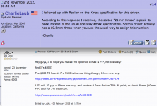
Nah, same layout, different size.
Thanks. Still amazingly small, for that LF extension. Given the Radian's power capabilities + it's sensitivity, I'd never get near the max excursion, so Id' surely be able to EQ it flat to 40 Hz, yes? Maybe with a steep HPF somewhere north of 30 Hz.
I could actually fit four of these in my truck, plus all my racks. Intriguing. (Makes me immediately consider building them as push-pull pairs, possibly by making them slightly taller.)
## BUT I HAVE A PROBLEM: On stage, I need as little depth as possible.
One solution would be to turn these sideways, openings facing each other but with a gap. (Maybe with a piece of braced-hardboard going across the back "opening," in-between them.)
However, it would be much better if the opening was on the side, like the Danley TH212. (My dream sub, except for the weight.)
Do you think that would work with this design?
Last edited:
However, it would be much better if the opening was on the side, like the Danley TH212. (My dream sub, except for the weight.) Do you think that would work with this design?
I don't see why not. Just make sure that the mouth is the same CSA that the design calls for.
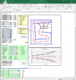
My biggest concern with the sim is the "compression ratio" (CR), which stands at 2.65 when cone compensation is included (it will be larger without). I've seen online recommendations to keep the CR to 2:1 or lower, but no objective basis is given for this recommendation, and there designs online that show much higher CRs, but no real measurements to indicate whether or not the high CR is causing any issues.
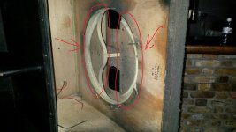
If I was going to build this thing (anyone want to send my a free Dayton ND driver? LOL), I'd build it and do distortion testing at different input levels, to see if it looks much different than I'd expect before published Xmax is reached. I'd also try different methods of loading the front of the driver to see if unequal pressures across the cone can be reduced. Methods like what CV used for their bass bins for example (see attached image).
Objective data really seems to be missing (or not easily accessible) about the CR issue.
Attachments
I just made a quick mod of your diagram, extending the top maybe 5", then adding a second angled horizontal divider above the baffle. (parallel to the baffle.) This would giver even pressure on the driver, and a slightly longer horn length, (the driver's output entring the new top section via the "right" side of the diagram.) I assume it would also lower the compression ratio a tad.
It might also allow for build a push-pull pair of these subs.")
Of course, the angles would have to be slightly modified, but it would still end up a VERY compact 15" horn, with respectable LF extension.
Sadly, I currently have no way of uploading a photo, but you understand, yes?
It might also allow for build a push-pull pair of these subs.
Of course, the angles would have to be slightly modified, but it would still end up a VERY compact 15" horn, with respectable LF extension.
Sadly, I currently have no way of uploading a photo,
but you understand, yes?
Last edited:
I've seen online recommendations to keep the CR to 2:1 or lower, but no objective basis is given for this recommendation, and there designs online that show much higher CRs, but no real measurements to indicate whether or not the high CR is causing any issues.
I recall the initial "simulation wars" (for lack of a better word) back in 2009 where a higher compression ratios sometimes was put forward as a good thing in general as the simulated response became flatter, and it is true that the upper out of pass band dip normally will be suppressed with higher compression, but to me that is the wrong approach as I believe that it might come at the cost of driver lifetime.
Driver fatigue can not be measured easily as it encompasses both thermal and mechanical components impacting driver over time, perhaps this is why it has not been put forward in clinical terms (evidence), but I agree that higher compression, although perhaps giving a better simulated response, can be a risky move, especially if the S1-S2 differ a lot (angled condition), only time will tell I guess.
A very elegant implementation of cone compensation into the design can be seen in the SS15 where it actually ads to the path length between S2 and S3 (simulation setup dependent).
At the time the THAM15 made was designed, almost ten years ago, our knowledge was on another level both regarding he simulation tool and the potential gains of a cone compensation, on the whole though I'm still very proud of the real world performance of the THAM series and the compromises we made in the balancing the designs (size/extension/SPL), and the fact that they still today, almost ten years later, are quite popular in the DIY community.
Driver fatigue can not be measured easily as it encompasses both thermal and mechanical components impacting driver over time, perhaps this is why it has not been put forward in clinical terms (evidence), but I agree that higher compression, although perhaps giving a better simulated response, can be a risky move, especially if the S1-S2 differ a lot (angled condition), only time will tell I guess.
I agree that something like "driver fatigue" as a by-product of a high compression ratio (CR) is something you'll only discover with time. But it should be possible to measure the effects of anything that would be contributing to that. For example, high and uneven pressure on the driver's cone should produce an increase in THD, and this is something that CAN be measured. Measuring the THD of the driver in free air up to the 10% limit, and doing the same with the driver mounted in the TH and correlating it with the driver's expected excursion at the drive level might help to highlight if this is an issue.
After doing some more reading on the subject, it seems that all the data I've come across wrt CR is either subjective or anecdotal in nature, but generally:
1. The smaller the driver's Sd, the higher the "highest recommended" CR. CD horns for example, could have CRs approaching 10:1. So is the 2:1 "rule" applicable to 18" drivers, 15" drivers, 10" drivers...?
2. The longer the horn, the lower the "highest recommended" CR (so it's not just dependent on Atc/S2). But there's little or no mention of what this dependency actually looks like. Is it a linear or logarithmic relationship, for example?
A very elegant implementation of cone compensation into the design can be seen in the SS15 where it actually ads to the path length between S2 and S3 (simulation setup dependent).
Adding in "cone compensation" should increase the CR though, as basically Vtc is being reduced in the process. In the current version of my THAM workbook (3.6), I'm calculating the CR as Atc/(S2+Vtc/W), where "W" is the width of the horn, in order to take into consideration the impact of Vtc on the CR. Interestingly enough, once you look at it that way, the CR of the Danley designs looks pretty high, but I haven't seen any complaints about "cone fatigue" with those designs. OTOH, Danleysound does use some pretty strong drivers in them!
The issue here is the Xmax. It's fairly low for a low Fb TL design. A 40 Hz Fb is probably as low as I'd go with that driver.
It does look nice for the price though
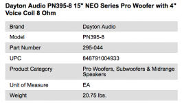
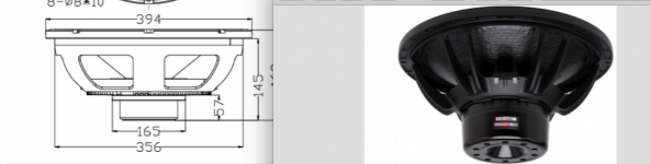
I'm guessing that with a 48mm p/p mechanical limit, the xmax of 6.5 mm is pretty conservative. They also have it listed at 25 lbs which is pretty heavy for an ND aluminum frame 15" driver
Mechanical limits and Xmax are separate ratings, doubtful that Dayton would be more "conservative" in rating this driver's 6.5mmXmax than any others.
Shipping weight might be 25lbs, though it appears net weight is 20.75lbs.
For comparison, the neo B&C 15SW115 with 13.5mm Xmax and 30Bl is 26.5lbs, 5.75lbs heavier, when you compare the depth of the magnet structures, easy to see where the weight and increased Xmax come from.
Regarding compression ratios, the PN395-8 Mms of 150g appears to be in line with drivers of similar Xmax used in horns.
Attachments
Last edited:
Mechanical limits and Xmax are separate ratings, doubtful that Dayton would be more "conservative" in rating this driver's 6.5mm Xmax than any others.
The Dayton PN395 has a 6.5mm Xmax and basically a 24mm Xmech, for a ratio of 0.27
The B&C 15SW115 has a 13.5mm Xmax and 30mm Xmech, for a ratio of 0.45
The specs on the Dayton don't include the length of the voice coil. With such a low ratio, I wonder if there's any danger of the coil actually leaving the gap on high excursion, which could have dramatic consequences if the cone rocks too much on the return stroke..
I had the same thought, but Dayton may make the voice coil former long enough to not leave the gap ;^).I wonder if there's any danger of the coil actually leaving the gap on high excursion, which could have dramatic consequences if the cone rocks too much on the return stroke..
The dangers are cone deformation, temporary (distortion) or permanent kinking or tearing.
2.5 to 1 should be no problem with a suitably heavy cone, but definitely is with a lighter cone. For instance the 139G Mms Eminence 4015LF sounded clean in a BR, but distorted in the Keystone (around 2.5/1 compression ratio), while the Dayton PA 385 at 172g Mms seemed cleaner, with 9 and 10mm Xmax respectively.
The Radian 2216 Neo more than double the Xmax (on paper) of those drivers, but may not have a heavy enough cone to withstand high compression ratios without "folding up" when pushed hard.
The PE website quotes the PN395's Mms as 150g, and the PA385's Mms as 230g. They both feature 4" coils.
The PA385 however has a longer Xmax, 10mm compared to 6.5mm, and a higher power rating (1kW compared to 800W), so a good chunk of that extra weight might be caused by the longer and perhaps sturdier voice coil.
PE boasts about the stiffness of both cones (the PA385 uses a kevlar/paper mix and the PN395 uses a fiberglass/paper mix), so I've left a question on their site, asking which of the two is stiffer.
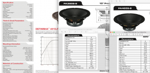
The Definimax 4015LF driver has a publishes Mms of 137g, a 4" coil and a 9mm Xmax, and a rating of 1.2kW. The cone is just "coated paper", according to the PE website. The specs suggest a much lighter cone than the PA385, as the Xmax is pretty close, and the power rating is actually high, suggesting that there might not be much difference between the weight that their coils are contributing to the Mms.
The PA385 however has a longer Xmax, 10mm compared to 6.5mm, and a higher power rating (1kW compared to 800W), so a good chunk of that extra weight might be caused by the longer and perhaps sturdier voice coil.
PE boasts about the stiffness of both cones (the PA385 uses a kevlar/paper mix and the PN395 uses a fiberglass/paper mix), so I've left a question on their site, asking which of the two is stiffer
.The Definimax 4015LF driver has a publishes Mms of 137g, a 4" coil and a 9mm Xmax, and a rating of 1.2kW. The cone is just "coated paper", according to the PE website. The specs suggest a much lighter cone than the PA385, as the Xmax is pretty close, and the power rating is actually high, suggesting that there might not be much difference between the weight that their coils are contributing to the Mms.
do you figure those cones are stronger than that of my 15pzb40? - does't matter as don't travel at all (like <100 mile per year) Also, when doing sims, what might be realistic coil temperatures for power compression.
https://i.imgur.com/tlfdstV.jpg
https://i.imgur.com/tlfdstV.jpg
do you figure those cones are stronger than that of my 15pzb40?
At an Mms of 123g, that driver has a lighter cone than any being considered here, including the Definimax driver.
1) The PE website gets some details wrong. According to the spec sheets, the 15" PA385 has 172.5Mms, the 18" PA465 225.1Mms, still less than 230g.1)The PE website quotes the PN395's Mms as 150g, and the PA385's Mms as 230g. They both feature 4" coils.
2)PE boasts about the stiffness of both cones (the PA385 uses a kevlar/paper mix and the PN395 uses a fiberglass/paper mix), so I've left a question on their site, asking which of the two is stiffer
3)The Definimax 4015LF driver has a publishes Mms of 137g, a 4" coil and a 9mm Xmax, and a rating of 1.2kW. The cone is just "coated paper", according to the PE website. The specs suggest a much lighter cone than the PA385, as the Xmax is pretty close, and the power rating is actually high, suggesting that there might not be much difference between the weight that their coils are contributing to the Mms.
2) The PA385 is pretty stiff compared to the Definimax 4015LF.
3) The spec sheet I have lists the 4015LF Mms at 137g, and Pe at 700 watts.
Though the higher power inside-outside wound PA385 coil may be heavier than the 4015LF, the cone is also.
The PA385s were record-breakers for the amount of stink the adhesives put out in the initial high power testing ;^).
Art
Attachments
Last edited:
I've emailed Dennis @ Radian, asking if he could perhaps join this forum and contribute to this particular thread. Hopefully he will.
Meanwhile, the data sheet for that Radian 2216 Neo 15" says
"EXCLUSIVE X5 TREATED & COATED CONE HAS INCREASED STRENGTH, IS TEAR RESISTANT, ALLOWS FOR A LOWER RESONANT FREQUENCY, IS WATERPROOF AND WON'T FADE IN THE SUN BECAUSE IT'S ULTRA VIOLET PROTECTED."
- their caps, not mine. Sorry.
So, well, there's hope, I guess.
Not much hope...I've emailed Dennis @ Radian, asking if he could perhaps join this forum and contribute to this particular thread. Hopefully he will.
So, well, there's hope, I guess.
Something about the Radian neo drivers had been bugging me- after a little research from around 6 years ago the reason they seemed too good to be true is because they listed the Xmax incorrectly, it's 21.3 MM peak to peak, not one way.
Hence the short magnet structure and a surround befitting a 10.65mm Xmax.
Radian 2218 NEO? 21mm x-max
Oh well, let's return to the regularly scheduled New Dayton Neo driver discussion...
Art
Attachments
1) The PE website gets some details wrong. According to the spec sheets, the 15" PA385 has 172.5Mms, the 18" PA465 225.1Mms, still less than 230g.
According to the spec sheet at the PE link below, it's 230g. Also, if you plug the parameters as published on the PE website into Hornresp, Mmd calculates to 220g, which is higher than the 172.5 Mms that you're quoting (Mmd should always be lower than Mms).
Link: https://www.parts-express.com/pedocs/specs/295-040s.pdf
I believe that there were some "issues" with the PA385 when it came out. One forum member purchased one and measured it, and the t/s params were quite a bit off published. Fs was right, everything else was way off, so it wasn't a matter of "break-in". With a bit of digging, it should be possible to find the thread in question.
If the PA385's Mms is actually 172.5g instead of 230g, this suggests even more that the cone of the PN395 might be pretty stiff, as stiff as that of the PA385, as that 22.5g difference between the Mms of the two of them could mostly be as a result of the PA385's longer, heavier coil.
Brian,
I like your design from post #16, but I have a depth restriction of 22”. How could I modify that design to accommodate?
Thanks
I was unable to find a solution that's 22" deep. You might have to look at a single-fold solution, or something like the Keystone. If anything, this driver wants a larger box, like this example - 26" deep and 22" wide
Attachments
- Status
- This old topic is closed. If you want to reopen this topic, contact a moderator using the "Report Post" button.
- Home
- Loudspeakers
- Subwoofers
- New Dayton Neo 15" I'm very excited about