Request moderators to delete schematic from post no. 332.
Here is the corrected schematic.
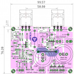
The stuffing guide and pcb and the bom is correct and remains same. These too are attached herewith for completeness.
regards
prasi
Here is the corrected schematic.
The stuffing guide and pcb and the bom is correct and remains same. These too are attached herewith for completeness.
regards
prasi
Attachments

Last edited:
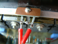
I think the schematic (or pcb) said to keep those diodes in contact with the heatsink.
Try clamping the diode leads to the heatsink, via a Kapton insulator; they offer a more thermally responsive access point to the PN junction than the diode body. I did this with three diodes on my version of the Leach.
Brian.
Attachments
This amplifier is a good start for beginners but not only.
Do you want a cheap simple good playing amplifier?
Do you want a low budget amplifier.
You don't like protection circuits?
You can't pay for giant heatsinks?
You can't pay for huge transformers?
You haven't scopes, multimeters, generators e. t. c?
Do you want to built something?
This amplifier is for you!")
Do you want a cheap simple good playing amplifier?
Do you want a low budget amplifier.
You don't like protection circuits?
You can't pay for giant heatsinks?
You can't pay for huge transformers?
You haven't scopes, multimeters, generators e. t. c?
Do you want to built something?
This amplifier is for you!
I have collected most parts, but missing 10kuF 63V in 30mm dia size (all are 35mm size). Based on thimios experience, I think atleast 10kuF is necessary.
Also dont have the 0.47ohm emitter resistors, but going to use 0.33 which I have in my parts bin.
Prasi, as you already can see, never i mound the rectifier diodes on the board.
I just use an existing psu.
I have used only cheap 3300uf/63v on the bord.
Just not connect the (-) POWER terminal together with the( -) RECTIFIER.... HUM.
I have used( -) of second capacitor bank.
Hum free.
I think 0R33 is ok.
Try clamping the diode leads to the heatsink, via a Kapton insulator; they offer a more thermally responsive access point to the PN junction than the diode body. I did this with three diodes on my version of the Leach.
Brian.
Hi Brian, thanks for the suggestion. Is that two pieces of Kapton, one on the bottom?
I think that using fast output transistors with retro topology, like this one, is asking for trouble with regard to oscillations. Even 70 MHz drivers are overkill. I suggest trying slower drivers and outputs. MJL4281 is overkill for this 25W amp. It's enough to use TIP35C. With them you won't need 10R base stoppers.
Last edited:
I'm looking to use a couple of 2SC5200 that I have extra from the VSQA.
It looks ok on the sim but is there anything obvious I am missing?
The Cob, HFE, fT and current handling are all lower but I couldn't see anything that would rule them out.. but I am new around here so may have missed something...
It looks ok on the sim but is there anything obvious I am missing?
The Cob, HFE, fT and current handling are all lower but I couldn't see anything that would rule them out.. but I am new around here so may have missed something...
Last edited:
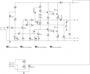
Hopefully someone could be kind enough to have a look at the Sim model for the AX-6.
I shamelessly downloaded it from Still4Given's post back at #194. There were issues that were discussed but I didn't see a fixed .asc so I tried to make the model fit the schematic.
Retro Amp 50W Single Supply
Besides what Mooly discussed back then, I found some caps were the wrong way around.
-------------------
I can't get the input past 0.45v before it starts to distort. Output is sitting around 35Vpp. THD at 1KHz is about 0.0553%. I got around 50mA bias (I think).
I've got a basic grasp of LTSpice but please let me know if I'm doing something wrong or maybe (miraculously), it is right ;-)
I shamelessly downloaded it from Still4Given's post back at #194. There were issues that were discussed but I didn't see a fixed .asc so I tried to make the model fit the schematic.
Retro Amp 50W Single Supply
Besides what Mooly discussed back then, I found some caps were the wrong way around.
-------------------
I can't get the input past 0.45v before it starts to distort. Output is sitting around 35Vpp. THD at 1KHz is about 0.0553%. I got around 50mA bias (I think).
I've got a basic grasp of LTSpice but please let me know if I'm doing something wrong
or maybe (miraculously), it is right ;-)Attachments
It seems that amp has high gain so it's not strange that 0,45V at the input is level for the max output. I don't think it's problem.
From memory
Power supply 50v.
0.890v RMS input give 18v RMS output before clip. using an 6 ohm dummy load.
So 18*18=324
324/6=54w RMS.
Ivanlukic, i'm using MJW0281G, i can't see any instability neither as heating not on scope.
Last edited:
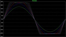
I've attached a screenshot of what the sim shows when I vary the input voltage from 0.4v to 1V. Does this reflect reality or am I doing it wrong?
Can someone please point me in the direction of R18 R16? I can't seem to figure out which ones they are on the attached schematic. (Too much blood in my caffeine stream I suspect!).
The gain is approximately equal to 1+(R18/R16) which is 45. Simulation bears that out with 64.4mv rms needed to obtain 2.86 volts output which is a gain of 44.5. The small discrepancy can be accounted for by the very small attenuation caused by R1 and the bias network.
Can someone please point me in the direction of R18 R16? I can't seem to figure out which ones they are on the attached schematic. (Too much blood in my caffeine stream I suspect!).
Attachments
hello avtech,
thank you for the sim file.
R16 sim = R4 pcb
R18 sim = R6 pcb.
is this what you are looking for?
to thimios,
what bias level did you test with? and what was the value of 27ohm bias resistor. From the sim I am getting a value of 68ohm to 82 ohm for bias of 20mA to 50mA.
i am rookie with spice too, but looks like it has plenty of second harmonic.
regards
Prasi
Last edited:
Thanks Prasi. I matched the PCB reference to the sim.. and guess what? They are labelled R18 and R16 Not sure why I couldn't see that before!!
Is it ok to reduce the gain by increasing the R16 to 330 or will that mess up something further down the chain? I'm just looking to make the input a little less sensitive. The sim looks ok with a small increase in THD (0.0592 vs 0.0553).
Not sure why I couldn't see that before!!Is it ok to reduce the gain by increasing the R16 to 330 or will that mess up something further down the chain? I'm just looking to make the input a little less sensitive. The sim looks ok with a small increase in THD (0.0592 vs 0.0553).
hello avtech,
thank you for the sim file.
R16 sim = R4 pcb
R18 sim = R6 pcb.
is this what you are looking for?
to thimios,
what bias level did you test with? and what was the value of 27ohm bias resistor. From the sim I am getting a value of 68ohm to 82 ohm for bias of 20mA to 50mA.
i am rookie with spice too, but looks like it has plenty of second harmonic.
regards
Prasi
Hi Prasi i have instal 33R in both positions because i haven't any 27R.
Bias is 20mA.
PS. I must check again to be sure for bias setting.
Last edited:
Thanks Prasi. I matched the PCB reference to the sim.. and guess what? They are labelled R18 and R16
Is it ok to reduce the gain by increasing the R16 to 330 or will that mess up something further down the chain? I'm just looking to make the input a little less sensitive. The sim looks ok with a small increase in THD (0.0592 vs 0.0553).
Looks perfect to try.
regards
Prasi
- Home
- Amplifiers
- Solid State
- Retro Amp 50W Single Supply