Richard, are those measurements taken with 150R source impedance? If so that seems unrealistic.
Why do you think 150 Ohm source or a Load is unrealistic? I am measuring out to MegaHz freqs?
What do you calculate or measure it to be?
-Richard
Last edited:
Hi Richard,
That isn't as serious as it might first sound. Heck, Marantz and others have done this by regulating the voltage amplifier section with a lot of headroom between the regulated output and the raw DC. There are separate windings for those regulators and you really can hear the difference. I suspect the worse the problem is, the more you can hear the difference the front end regulation makes. As for the current supply, variations would only be heard near clipping. If you're running the system that hard, you ain't listening to music.
-Chris
Has anyone ever tried using a 7A22 as a mic preamp?
I have it's uncle, the 3A9 in my 561B scope. I think the trace output might be a weak point as it's just a 1-transistor buffer. I did listen to it once, but it was half-hearted and I don't remember what kind of test I was doing.
Why do you think 150 Ohm source or a Load is unrealistic? I am measuring out to MegaHz freqs?
What do you calculate or measure it to be?
-Richard
Not really sure how the measurements were taken or what they are of. I think you would find it difficult to get better than 6db/oct filtering out of a passive series filter, which is what a CM filter is. When you say isolation I assume you mean common mode filtering.
Not really sure how the measurements were taken or what they are of. I think you would find it difficult to get better than 6db/oct filtering out of a passive series filter, which is what a CM filter is. When you say isolation I assume you mean common mode filtering.
OMG. See # 5288, above.
-Richard
Hi Richard,
As for the current supply, variations would only be heard near clipping. If you're running the system that hard, you ain't listening to music.
-Chris
Have you measured it? Audio modulation on the ac line? Is it higher or lower than HF/RFI/EMI etal on the ac line caused by smps?
-Richard
Last edited:
I was only partly serious, Demian noted that Tek had nailed the PS problem years ago so why is it such a problem now?
Early SMPS were generally low frequency, used slow switching devices and were relatively inefficient by today's SMPS standards. My trusty Tek 2465 scope has an SMPS running at 50KHz, pretty elaborate filtering on the input and output as well as complex regulators, and yeah, the manual is an education itself!
These days, the DoE Level VI standard effectively makes it illegal to import inefficient SMPS, and as we all know, just about all electronics these days are imported.
The steps one takes to make a EMI quiet SMPS are in many ways opposite from making one small and efficient. The two types of EMI generated by a SMPS (sw. freq + harmonics, and ΔV/ΔT broadband EMI) caused respectively by high switching frequencies and fast device transitions are the modern way to make a SMPS small and efficient. The net result of the DoE standard and SMPS design is a flood of imported SMPS with high EMI and the FCC is too defunded to enforce Part 15. As a ham it is truly disturbing.
(old story time) The first SMPS I ever designed in 1988 was a 200 W unit for a mobile 100 W power amp, and it ran at 25 KHz, generated a lot of heat and required a toroid almost 2" in diameter but passed all testing. When TDK announced a new HF ferrite a few years later I redesigned that amp's power supply to run at 100 KHz (I think the highest in mobile audio amps at the time) and was able to use a little over 1" diameter toroid. The biggest surprise with that design was how it interfered with AM radios (duh). We had to recall the amps and retrofit them with LC power input filters...expensive mistake.
These days the switching magnetics and devices have become very specialized and to make a truly low-RFI supply meeting DoE efficiency specs requires exacting construction techniques and materials. A good starting book on the subject: Fundamentals Of Power Supply Design by Mammano gives a peek into some of the compexities behind a proper SMPS design.
Cheers,
Howie
A friend told me they compared the Oppo to a Bel Canto and some other CD players. With an external DAC, the Oppo still sounded bad to them.
Bel Canto is pretty well designed stuff... he's been able to make better sounding gear from DAC's and stuff other people scoff at.
While I know this sounds dumb since bits are bits, I don't at all suspect placebo. Although Bel Canto had the balls to post jitter measurement, and I don't see that with Oppo specs (the recent ones, maybe old ones did?).
I didn't see the latest measurement posted as CMR, IE CM to DM conversion. That's more clear.
I'm sure it works great, just trying to figure out how you are characterizing it. There is DM noise, CM noise, conversion back and forth, etc. I have no sense of scale for what's good or bad or what is necessary to make an improvement. I do know that for CMR to matter, DMR must also be good enough and vise versa.
I can think of a few potential secret sauces depending on what you do with the trafo shield and adding extra windings to the CMCs. But I have no knowledge of isolation trafo construction techniques.
A friend told me they compared the Oppo to a Bel Canto and some other CD players. With an external DAC, the Oppo still sounded bad to them.
good to know it isnt just myself. I used external DAC and fiber optic output from OPPO also... sound was bad. So, now I am trying to extract the L and R from the HDMI... which indications from OPPO suggest it is best source for highest quality sound. We shall see.
-Richard

OK. Here are two examples: A Computer and CD player. When you monitor the power cord with a spectrum analyzer you get these freqs (to 1.25MHz) and 100uv at base and 10db per division.
When Computer is OFF, there is no signal.. base line. Turn the Computer ON and you get this junk. Some strong idle tones.
Here is a CD player --> not playing... just ON.

THx-RNMarsh
Last edited:
Why do you think 150 Ohm source or a Load is unrealistic? I am measuring out to MegaHz freqs?
What do you calculate or measure it to be?
-Richard
150 ohms is not representative of a real world application and the results
will reflect that.
https://www.schaffner.com/fileadmin...note/Schaffner_AN_CISPR17_Measurements_E8.pdf
T
Under 250V, a 150 ohm load is 400W. Why, not representative ?150 ohms is not representative of a real world application and the results
will reflect that.
If you do not use the exact type of transformer I said, you wont get any where near the DM and CM numbers I get. But, yes, there is another ingredient which improves the rejection and isolation a lot and to higher freq. No, I'm not telling. But, as told, you will get very good results especially with the filter included in between.
One reason I rarely suggest doing something in detail is because HERE one only gets arm chair critism without trying it... without listening.
THx-RNMarsh
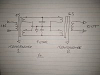
There are certainly a few ways to implement this arrangement of back to back connected transformers. Below is one way that would net good results. The interconnection is balanced as is the filtering. It might also be worth using an RC snubber in there.
The best transformers from a noise isolation POV are split bobbin = low P->S capacitance. You can go further with electrostatic shielding and even further with full Farady shielding. I've actually made these on split bobbin transformers as I used to work at a specialist transformer manufacturer.
If you do ES or Farady cage on split bobbin watch out for shorted turn. There needs to be small slit in the shield / cage.
T
Attachments
Under 250V, a 150 ohm load is 400W. Why, not representative ?
The source impedance is what is important.
T
150 ohms is not representative of a real world application and the results
will reflect that.
https://www.schaffner.com/fileadmin...note/Schaffner_AN_CISPR17_Measurements_E8.pdf
T
Of course we dont filter out 50-60 Hz ! You look towards the Z at higher frequencies.
What do you measure for the ac line Z? With and without isolation transformers.
THx-RNMarsh
There are certainly a few ways to implement this arrangement of back to back connected transformers. Below is one way that would net good results. The interconnection is balanced as is the filtering. It might also be worth using an RC snubber in there.
The best transformers from a noise isolation POV are split bobbin = low P->S capacitance. You can go further with electrostatic shielding and even further with full Farady shielding. I've actually made these on split bobbin transformers as I used to work at a specialist transformer manufacturer.
If you do ES or Farady cage on split bobbin watch out for shorted turn. There needs to be small slit in the shield / cage.
T
Yes, that has potential, also. I also stated the split bobbin like I show and said is needed.
Have you any measurements?
I hope people apply the AC isolation/filtering concept to their music systems. Or what is the point in even talking about it?
-RM
Last edited:
What are the axes on those measurements? And how did you couple to the power cord?
Thanks...
Wide band Inductive probe coupled to network/spectrum analyzer.
-RM
Last edited:
- Status
- Not open for further replies.
- Home
- Member Areas
- The Lounge
- John Curl's Blowtorch preamplifier part III