Ian,
My ultracaps project you saw (powering ALL dac-voltage rails separately, and ALL other voltage rails for fifo II/Isolator/dualXO II/ etc. as well) is also based on COOPER BUSSMANN HV1635 but the 100F version. They are not the best ultracaps, the Maxwells are much better, so can you imagine how yours perform
Btw, please do NOT go the LPS-1 route, since they still use regulation which ruins the perfect ultracaps specs!!!!!
My wish for you to design:
Design a circuitry, microprocessor driven, with the possibility to set a LOW threshold Voltage to switch between two banks of ultracapacitors. Switching devices based on VERY LOW RDS-ON MOSFETS, capable of switching several Amperes for fast charging.
It also would be nice if design also could handle voltages up to 60V for powering power amps, AND ESPECIALLY for DRIVER AMP circuitry!!!
This way we also could use this design to power the DRIVER AMP section in our power amps, which will make a HUGE difference in SQ!!!
And last, but definitely not least, this could be the holy grail to power output stages.....
About your concern overpowering the ultracaps while switching, when microprocessor controlled, you could build-in a very short delay time, which will be compensated by a good buffer elco at it's output, that is what I use to prevent hick-ups in power delivery while switching the banks.
I am VERY sure you would have a HUGE hit on the DIY audio market, and MANY people would be interested in buying such a design, including myself!!
Before I forget, since Class-D designs are "the new thing", it is very good possible that in the near future there will be new Class-D designs which CAN surpass Class-A Mosfet amplifiers SQ. ALL Class-D amplifiers do prosper from GOOD power source. So, can you imagine how a GOOD Class-D amp would sound if powered by Ultracaps?
About Mosfets for switching, ST for example has a 60V 120A 0.0024 RDS-ON mosfet which would be a very good choice!
http://www.st.com/content/ccc/resou...df/jcr:content/translations/en.CD00272622.pdf
Don't forget using them for positive AND ground circuitry!
Btw, Powerex Incorporated has switching mosfet modules with 177 micro ohm rds-on,,,,, so maybe there are other contenders on the market too….
Keep up the good work Ian
Best regards,
Alex
+1
Here are some LPS-1 measurements:
UpTone LPS-1 Linear Power Supply Review and Measurements | Audio Science Review (ASR) Forum
UltraCapTM LPS-1 is mainly a balance board, you can purchase it yourself.
Thanks! I will try it. How do you charge them?
please do NOT go the LPS-1 route, since they still use regulation which ruins the perfect ultracaps specs!!!!!
Yes, I spotted that. Same also for all the others I've looked at, eg Bakoon, see here:
Such a shame to cripple a great idea!
About the principle of charging, it is a very simple method, at least, the one I use.
The idea came from my friend Balazs at Headfi forum, see his thread:
R2R DA M1 Ultracap powered build | Headphone Reviews and Discussion - Head-Fi.org
What I use is a simple laptop adapter, 19V 4,6A which I connect to a DC-DC converter, a CC/CV type (Constant Current/ Constant Voltage). This converts 19V to the preset needed voltage for your ultracaps. That is all I use CC/CV because otherwise DC-DC converter gets overloaded, and this way I can use one laptop adapter and spread it's current over several DC-DC converters to charge several ultracap psu's at the same time.
The idea came from my friend Balazs at Headfi forum, see his thread:
R2R DA M1 Ultracap powered build | Headphone Reviews and Discussion - Head-Fi.org
What I use is a simple laptop adapter, 19V 4,6A which I connect to a DC-DC converter, a CC/CV type (Constant Current/ Constant Voltage). This converts 19V to the preset needed voltage for your ultracaps. That is all
I use CC/CV because otherwise DC-DC converter gets overloaded, and this way I can use one laptop adapter and spread it's current over several DC-DC converters to charge several ultracap psu's at the same time.Ian
Did you measure the voltage across each cap?
I expect that the "balance boards" are voltage regs, that limit the voltage across the cap so you don't exceed their ratings.
A fairly simple circuit to build.
The dual bank/switching aspect of the LPS-1 sounds cool, but seems like overkill to me.
I would do the same thing I started doing recently for putting lifepo4's in series, make a little reg for each cell, that controls the voltage on that cell.
I found a simple circuit using a tl431 and a pnp and adapted it for my application. There is also a LM317 in front of this, that I use to current limit the voltage I feed to the regs.
Randy
Ian
Did you measure the voltage across each cap?
I expect that the "balance boards" are voltage regs, that limit the voltage across the cap so you don't exceed their ratings.
A fairly simple circuit to build.
The dual bank/switching aspect of the LPS-1 sounds cool, but seems like overkill to me.
I would do the same thing I started doing recently for putting lifepo4's in series, make a little reg for each cell, that controls the voltage on that cell.
I found a simple circuit using a tl431 and a pnp and adapted it for my application. There is also a LM317 in front of this, that I use to current limit the voltage I feed to the regs.
Randy
There's no need to measure the voltage on each ultracap since whitepapers of Maxwell says that when using MORE than 3 ultracaps in series you need balancing boards.
Balancing cane be done active and passive, for circuitry below 3x2.7V there's no need for balancing.
Switching banks isn't overkill, it just is convenient not having to disconnect and connect discharged and charged ultracaps the whole time.
Further, this design, based on switching banks, can also be used for power hungry applications, as stated above.
I myself would love to see a design which can be used in other applications as wel, not only for powering XO's.
Correctly speaking, ultracapacitors cannot be compared with LDOs because the complete LPS with ultracapacitor is still indispensable to LDOs. Both the input and the input of LPS with ultracapacitor requires LDOs to ensure the voltage, otherwise the ultracapacitor will be very easy damaged. At the same time, in the LPS with ultracapacitor, it is also necessary to specifically protect LDOs, otherwise, the residual capacity of ultracapacitor may destroy LDOs when it is turned off. In addition, LPS with ultracapacitor still need to use electrolytic capacitors for complementary performance. In short, a well-designed LPS with ultracapacitor is not easy, if not very familiar with LPS, it is recommended not to try, otherwise it will burn out a lot of ultracapacitor, wasting a lot of time and money.
There's no need to measure the voltage on each ultracap since whitepapers of Maxwell says that when using MORE than 3 ultracaps in series you need balancing boards.
Balancing cane be done active and passive, for circuitry below 3x2.7V there's no need for balancing.
Switching banks isn't overkill, it just is convenient not having to disconnect and connect discharged and charged ultracaps the whole time.
Further, this design, based on switching banks, can also be used for power hungry applications, as stated above.
I myself would love to see a design which can be used in other applications as wel, not only for powering XO's.
Passive balancer works good for me. Based on my test, the voltage difference between two ultracapacitors is within 2% all the time when use passive balancer. I use CC then CV for charging method.
A little bit worry about active components for audio applications. But I could be wrong.
Ian
Last edited:
I guess I’ll just toss this one out there.
I will be needing a psu to power both the dac and the RPi with a internal hdd. So, if anyone is building something suitable. I’ll be very interested.
If this Super Cap solution can do it, I’m loving it. But I’ll have to admit, designing real high quality psu’s are beyond my current abilities. So, as long as there is a “complete“ solution I’ll be all over it. [emoji4]
And I try to follow the KISS principle as much as possible.
P.S. I’m realizing that the case I got in the beginning isn’t going to cut it. This “tiny” RPi dac is getting pretty big for something so small. Lol
Last edited:
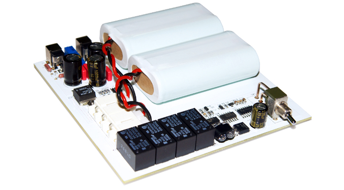
For the ones interested, here are some pics from my project, dismantling ultracap powered AK4495 dac, and building ultracap powered dac with 8x DA-M1 modules, FIFO 2/IsolatorPi/DualXO 2/
DA-M1 Ultracap powered - Google Drive
DA-M1 Ultracap powered - Google Drive
Passive balancer works good for me. Based on my test, the voltage difference between two ultracapacitors is within 2% all the time when use passive balancer. I use CC then CV for charging method.
A little bit worry about active components for audio applications. But I could be wrong.
Ian
Cool, then you don't need a vreg for each cap, just one for the circuit.
Trying to get 5v out of two lifepo4 batteries, one goes to 3.3 and the other to 1.7 if you don't regulate individually.
A current regulated vreg will do CC then CV, so sounds like the same as I would do.
Randy
A little bit worry about active components for audio applications. But I could be wrong.
Ian
What do you mean? Active balancing the ultracaps? There's no need for balancing at all when using 2 or 3 in series.
And, to be sure, I use SAFE voltage to start with, and of course, starting voltage highly depends on voltage margin of host.
For example, 3.3V host works between 3.1V and 3.5V, need two ultracaps, and starting voltage (CHARGING voltage) is 3.5V. Both ultracaps get a max of 1.75V.
For example, 5V host works between 4V and 5.5V, need two ultracaps and starting voltage (CHARGING voltage) is 5.2 V to be on the safe side. Both ultracaps get a max of 2.6V. Depending on the host and power consumption, you could charge at even lower voltage.
The problem I encountered was more on the side of the DC-DC converters, most cheap ones with V and A display couldn't finetuned at 1.8V, so I damaged two host modules (DA-M1) because Voltage shifted to 2V....
So, be careful, what you charge is at OUTPUT.
That said, maybe it is possible to set a HIGH voltage threshold to? That would have to be some sort of overvoltage protection circuit.....
Last edited:
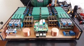
120x 100F ultracaps in operation
An externally hosted image should be here but it was not working when we last tested it.
What do you mean? Active balancing the ultracaps? There's no need for balancing at all when using 2 or 3 in series.
And, to be sure, I use SAFE voltage to start with, and of course, starting voltage highly depends on voltage margin of host.
For example, 3.3V host works between 3.1V and 3.5V, need two ultracaps, and starting voltage (CHARGING voltage) is 3.5V. Both ultracaps get a max of 1.75V.
For example, 5V host works between 4V and 5.5V, need two ultracaps and starting voltage (CHARGING voltage) is 5.2 V to be on the safe side. Both ultracaps get a max of 2.6V. Depending on the host and power consumption, you could charge at even lower voltage.
The problem I encountered was more on the side of the DC-DC converters, most cheap ones with V and A display couldn't finetuned at 1.8V, so I damaged two host modules (DA-M1) because Voltage shifted to 2V....
So, be careful, what you charge is at OUTPUT.
That said, maybe it is possible to set a HIGH voltage threshold to? That would have to be some sort of overvoltage protection circuit.....
Ultracapacitor may has some internal leakage. That leak current can cause unbalanced voltage when ultracapacitors are in serial. That's why we need balancer. The simplest passive balancer is just same volume resistors in parallel with each ultracapacitor cell. Have to make sure the current going through at least 10 times greater than the internal leak current.
Passive balancer works perfectly with CC-CV charger.
Ian
120x 100F ultracaps in operation
An externally hosted image should be here but it was not working when we last tested it.
That's a serious configuration have trouble breathe here
...in your link seems broken allow me below upload one of those nice goggle drive pictures to diyA own servers Attachments
I guess I’ll just toss this one out there.
I will be needing a psu to power both the dac and the RPi with a internal hdd. So, if anyone is building something suitable. I’ll be very interested.
If this Super Cap solution can do it, I’m loving it. But I’ll have to admit, designing real high quality psu’s are beyond my current abilities. So, as long as there is a “complete“ solution I’ll be all over it. [emoji4]
And I try to follow the KISS principle as much as possible.
P.S. I’m realizing that the case I got in the beginning isn’t going to cut it. This “tiny” RPi dac is getting pretty big for something so small. Lol
Besides the monster ultracapacitor power supply, I'll do something really light for RPi with those new gears. That would be interesting.
Ian
120x 100F ultracaps in operation
An externally hosted image should be here but it was not working when we last tested it.
is that audio gd's r2r dacs i see in there?
heres some class a f5 mono clones done with lifepo4
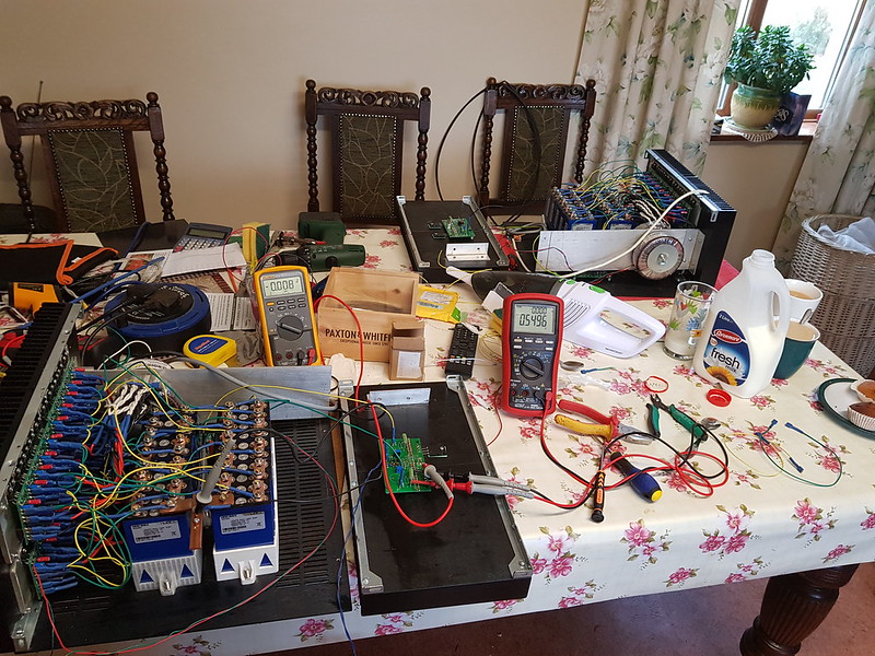
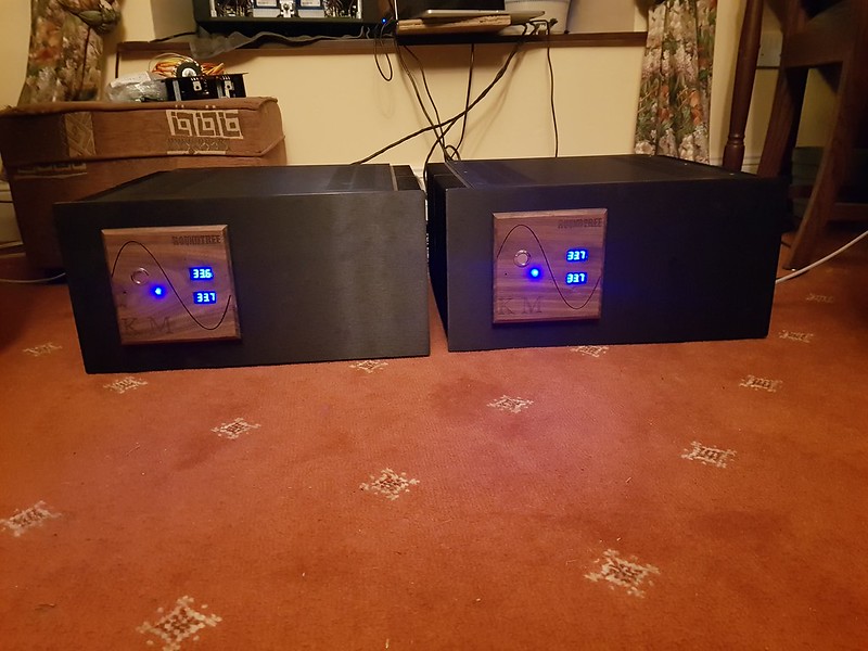
could be interesting to do similar with supercaps
should be simplier
is that audio gd's r2r dacs i see in there?
heres some class a f5 mono clones done with lifepo4
could be interesting to do similar with supercaps
should be simplier
Nice dining table
.What kind of is your LiFePO4 batteries?
Ian
- Home
- Source & Line
- PC Based
- ES9018K2M, ES9028Q2M, 9038Q2M DSD/I2S DAC HATs for Raspberry Pi