Maybe a more informative test would be to run .wav files through a simulation with different integrator settings and compare integrator distortions in the output.
All these tricks should not be necessary, I wish I could get our CAD dept to entertain adding this feature to LTSPICE. We simply add a directive to lockstep a transient analysis to FFT mode and force it to not interpolate points ever. The FFT's always have -300dB floor with no false harmonics. The software figures it out without the user having to guess on settings of multiple internal variables.
Another IMO LTSPICE bug
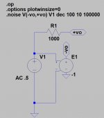
My second one this month, though I consider this one more serious. The .noise card ignores the AC gain of the referred to input source causing wrong answers or at least ambiguous answers. The circuit below will yield a 0dB gain to the differential output voltage in an .ac analysis but the referred to input noise of the 1k resistor is 2nV in the .noise analysis. Since the noise analysis uses an ac analysis to compute all the contributions I consider this a problem.
My second one this month, though I consider this one more serious. The .noise card ignores the AC gain of the referred to input source causing wrong answers or at least ambiguous answers. The circuit below will yield a 0dB gain to the differential output voltage in an .ac analysis but the referred to input noise of the 1k resistor is 2nV in the .noise analysis. Since the noise analysis uses an ac analysis to compute all the contributions I consider this a problem.
Attachments
Last edited:
I would make an allpass buffer using an E-source, and then run a sine wave .wav file through it. Make a new .wav file for each integrator setting, then compare the .wav files in Audacity or Baudline or whatever you like.
I guess you should also add a complex load to the buffer.
I guess you should also add a complex load to the buffer.
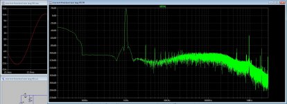
I've done this and found something interesting. The trapezoidal integration methods generate odd harmonics of the fundamental, whereas the gear method generates a bit less harmonics, but it does cause much more intermodulation with the samplerate or 1/timestep.
If the simulation length is locked to the FFT size, both methods have the same noise floor (although gear will have more intermodulation). But if the simulation length is different from the FFT size, gear will have a lower noise floor due to less intermodulation (at the penalty of some harmonics at very low level).
For some reason I get a high noise floor when I use a sine V-source with the default integration method. The output of the V-source is perfect, but the output of the allpass is noisy. Using gear fixes this, but again at the cost of more harmonics.
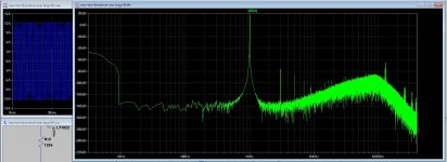
In all these cases the intermodulation and harmonics are because the sine frequency wasn't locked to the simulation length and timestep. When all 3 are locked, I get no harmonics and no intermodulation, just a bit of fuzz at the highest BW of the FFT.
Furthermore the distortions decrease the more datapoints there are per cycle. I rarely use more than 10 cycles for a simulation.
If you run say 100 cycles instead of just 10 cycles you start to get into integrator errors if you don't use frequencies that aren't multiples of your 1/timestep. But if you just use 10 cycles like I always do, there's almost no difference between gear or trapezoidal, or if your test frequency isn't aligned with your 1/timestep. This works well even if your simulation length isn't the same as your FFT size.
So if you're just doing THD simuations, don't run much more than 10 cycles.
If you're doing long simulations with many cycles maybe method=gear is better for you.
If the simulation length is locked to the FFT size, both methods have the same noise floor (although gear will have more intermodulation). But if the simulation length is different from the FFT size, gear will have a lower noise floor due to less intermodulation (at the penalty of some harmonics at very low level).
For some reason I get a high noise floor when I use a sine V-source with the default integration method. The output of the V-source is perfect, but the output of the allpass is noisy. Using gear fixes this, but again at the cost of more harmonics.
In all these cases the intermodulation and harmonics are because the sine frequency wasn't locked to the simulation length and timestep. When all 3 are locked, I get no harmonics and no intermodulation, just a bit of fuzz at the highest BW of the FFT.
Furthermore the distortions decrease the more datapoints there are per cycle. I rarely use more than 10 cycles for a simulation.
If you run say 100 cycles instead of just 10 cycles you start to get into integrator errors if you don't use frequencies that aren't multiples of your 1/timestep. But if you just use 10 cycles like I always do, there's almost no difference between gear or trapezoidal, or if your test frequency isn't aligned with your 1/timestep. This works well even if your simulation length isn't the same as your FFT size.
So if you're just doing THD simuations, don't run much more than 10 cycles.
If you're doing long simulations with many cycles maybe method=gear is better for you.
I afcouse do not have so much knowledge of LTspice, and learing it is quite a big process, but I like to see what you have done and how, I think because I am over 60 learning is slowed down a little.
For triangles I think generate it digital give a better quality and not much harmonics,, for example a pic and an lookup table, do exclude some electronics. I have seen yes within LTspice that I have uneven harmonic generation, the open loop version specially does that.
thanks for all help you guys .
Thanks for advice, I go try gear to see what happens.
regards
This is not bad, not bad at all, but only with the fase shifted 3 level version, only prefeedback in Ltspice, presume perfect low pass, did wel with high PSRR also.
if it sounds wel, I do not now, maybe it sounds very clinical because of such low distortion in LTspice, but can try, it is quite simple.
So now go on with the investigation thread.
regards
Attachments
Don't be afraid to build an amp because it has low distortion. I never found low distortion to be a bad thing unless there was something particularly unpleasant about my speakers I needed to mask.
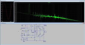
Here is the simulation I used. I run the simulation and then do an FFT of the result. LTSpice's own sine generator is better than the .wav file, so I stopped using it eventually.
I always use the Blackman window for the FFT, it has a very good combination of merits.
Here is the simulation I used. I run the simulation and then do an FFT of the result. LTSpice's own sine generator is better than the .wav file, so I stopped using it eventually.
I always use the Blackman window for the FFT, it has a very good combination of merits.
Attachments
I have some doubts about feedback, I have seen en hear on the hybrid I use here the without the sound is much easyer to listen to, so much more air, and the new hybrid has even more with the new all plate followers incl the mosfet drivers. but that are tubes these do better in LTspice also, a all fet or bipolair will sound bad without feedback, but class D open loop maybe not.
Thanks for the file, looks interesting, so I need to sim mine amp make a wav and put these through your schematic to see the result? because mine schematic sims very slowly that is why you use that bandfilter.
You have much more knowledge about LTspice, thanks for sharing your wisdom with me.
Do you lengthing your wav file with software? because making such file in LTspice using mine schematic take a lot of time.
regards
Last edited:
Yes I did also, but give ticks, maybe I did it wrong.
Hmm little english errors above, oke, the cycles, do I put 10 cycles in the voltage source to get what you advice? and extent it with audicy. in your ltspice file where to probe it, and do I need to connect the source who read the wav and disconnect the other one.
thanks
Hmm little english errors above, oke, the cycles, do I put 10 cycles in the voltage source to get what you advice? and extent it with audicy. in your ltspice file where to probe it, and do I need to connect the source who read the wav and disconnect the other one.
thanks
That's not what I meant. I usually simulate power amps for 10 cycles of the sine wave to get an FFT. The sine wave file I included in the .zip is 10 seconds long.
Your usage with class D is different from what I normally do. I'm curious, if you could provide a simulation file I would like to see how the simulator acts, maybe I can help.
Your usage with class D is different from what I normally do. I'm curious, if you could provide a simulation file I would like to see how the simulator acts, maybe I can help.
That's not what I meant. I usually simulate power amps for 10 cycles of the sine wave to get an FFT. The sine wave file I included in the .zip is 10 seconds long.
Your usage with class D is different from what I normally do. I'm curious, if you could provide a simulation file I would like to see how the simulator acts, maybe I can help.
Ahh oke, I give you the file, I am not so good in LT spice knowledge, what make it a little confusing. I have included a very long simulation, so you see what happens all the way. LTspice is quite advanced so help is always welcome.
thanks for the help.
kees
Attachments
Last edited:
Here also the 5 level, thanks to look at it, it is very interesting to simulate but I think it hust put more distortions in spice it has more steps where crossover can occur, just this is interesting to see in your sims I think..
have a nice weekend.
have a nice weekend.
Attachments
The circuit
Here I have the stuff, put the models in darlington under C:\Users\Administrator\Documents\LTspiceXVII\lib\sym\Darlington folder.
Or rename it for your own, contains the MJ transistors.. MJE15024 15025 are also big transistors from motorola withstand 250volts but are 16 amp and no darlington however there is a nice super emittor follower for that..
and the cmp file you have to relace in C:\Users\Administrator\Documents\LTspiceXVII\lib\cmp
regards
Attachments
This is using TIP121/127 models. The 2SC4102 is included with LTXVII, if its not present in LTIV then you'll have to choose something else.
Should click and run, just keep everything in the same folder. Set the bias to the recommended for the amp.
Mooly, truly awesome. Loads and runs! Sweet! Thanks
Here a correction, I did made the ASY wrong, in last post sorry, has two npn.
I have included the MJ darlingtons, and it do sim nice, when using original like you ask, then do copy cmd file to lib for new models I did already include but you can also use the new one from #Mooly and include only the MJ transistors
all is included in mooly zip file, if you do not mind mine hijacking Mooly?
regards
Attachments
Last edited:
- Home
- Design & Build
- Software Tools
- Installing and using LTspice IV (now including LTXVII), From beginner to advanced