Member
Joined 2009
Paid Member
Don't make me laugh, you are the Master at this!I would say that compensation is the most difficult aspect of amp design and I'm not wonderful at it

Hi Hugh,
Thanks for the informative post about the compensation fb cap.
I'll try it to digest later this evening, after dinner")
In the meantime I did some additional ac analysis because my ac graphs were different from yours.
The differences were due to the KSA992/2N5401 used and the BC847 snubber(47pF+3.3k).
I've made three simulations, all with the same 18pF fb cap.
The only difference are LTP transistor used and BC847 snubber
1) LTP with KSA992
2) LTP with 2N5401
3) LTP with 2N5401, BC847 without snubber
I've also plotted the Vvas, on that the phase is much more pronounced.
I think it's very difficult to have a correlating simulation with reality because we'r playing here in pico-land and those pico's are everywhere in the real world
For the Ixys models:
I put the file in the same dir as the simulation file and add a ltspice .inc directive: .inc ixys_lib.txt
In LTspice I add the general component nmos or pmos,
ctrl + right-click on the component and change value to the modelname.
Regards,
Danny
Thanks for the informative post about the compensation fb cap.
I'll try it to digest later this evening, after dinner
In the meantime I did some additional ac analysis because my ac graphs were different from yours.
The differences were due to the KSA992/2N5401 used and the BC847 snubber(47pF+3.3k).
I've made three simulations, all with the same 18pF fb cap.
The only difference are LTP transistor used and BC847 snubber
1) LTP with KSA992
2) LTP with 2N5401
3) LTP with 2N5401, BC847 without snubber
I've also plotted the Vvas, on that the phase is much more pronounced.
I think it's very difficult to have a correlating simulation with reality because we'r playing here in pico-land and those pico's are everywhere in the real world
For the Ixys models:
I put the file in the same dir as the simulation file and add a ltspice .inc directive: .inc ixys_lib.txt
In LTspice I add the general component nmos or pmos,
ctrl + right-click on the component and change value to the modelname.
Regards,
Danny
Attachments
Last edited:
Danny,
I am still struggling with the models. I had them going nicely, but now it escapes me. A few days will see this through.
I have drawn up a primer on amp stability which should help what we are dealing with.
1. Amplifiers are unstable when they have more than unity gain at a frequency where the phase shift, front to back, has reached 180 degrees.
Most amps use global negative feedback to improve parameters like FR, distortion, bandwidth, and noise. NFB brings a portion of the output back to the input stage where it's mixed with the input again to create an error signal which drives the output to intended gain. The factor by which the improvement is highly related to the ratio of the open loop gain (amp very high gain with NO feedback) to the closed loop gain (the specified gain which is typically 20-30dB).
2. Typically the Open Look Gain (OLG) of a linear amplifier might be 60dB, and closed loop gain might be 25dB (CLG). The division of these parameters(a difference in log db) of 35dB is the LOOP gain. This is the additional amp gain which is available to the amplifier as it works within its CLG, and this additional reserve reduces the distortion, noise and improves the bandwidth and FR.
3. Any signal passing through any amplifier (typically in nS) inevitably meets delay, and each stage adds a little 'lag', delivering, at output, an accumulated phase shift with respect to the signal at the input. It is always a lag delay, because no signal can appear at the output BEFORE it enters at the input!! This phase shift is then negative, and is higher as frequencies rise. It is expressed in degrees (360 degrees to a full waveform) since the period of the waveform is much less at higher frequencies.
4. At 1MHz, a typical amplifier would have a phase shift of -100 degrees from the input zero datum point. When this phase shift increases with rising frequency to the magic 180 degrees, somewhere around 2MHz, the negative feedback presented to the inverting input stage amplifier point has effectively now positive feedback. But if we add a tiny pF compensation cap across the input/output of the voltage amplifier, the gain of the amp at this frequency would be less than UNITY. Now, when the input stage is mixed this 'reverse', reduced phase output from the output stage, it decreases its error signal, which then reduces the amplifier output to avoid oscillation. This 'reversed' feedback is actually positive feedback, but it is not dangerous because the amplifier at this high frequency has less than unity gain, so it cannot oscillate and destroy the output stage.
5. Without a lag compensation capacitor to pull the amp gain below unity at the 'magic' 180 degree phase shift within a few uS this situation explodes into full blown oscillation. Without any signal limitations, this phenomenon quickly destroys the amplifier output stage since the level of the up and down waveform is forced rail to rail, causing destruction within a few uS. This must be avoided in any cost.......
6. Reducing the amp's gain to less than unity by the 'magical' 180 degree phase shift frequency is crucial to the stability and reliability of the amplifier. It also changes the sound quality of the amplifier if it is too high, or too low. It's dimension is critical, and it should be npo ceramic, polystyrene, or silver mica. The simple way is to install a small picofarad cap between the input and output of the voltage amplifier, collector to base on a single VAS. This pulls back the gain of 6dB per octave, starting a little lower than 20KHz and bringing the gain back to 0dB by at highest around 1.5MHz. If unity gain frequency is say 2MHz, we dimension this cap to deliver unity gain at slightly less than 2MHz. If this cap is too small, the amp will break out into short term transient, a transition between stability and destruction. If too large, the amp sounds leaden, and slow, and dull. Much of the poor sound of conventional linear amplifiers can be attributed to overlarge lag compensation.
7. A better way of compensating a linear amplifier is to use phase lead. This was mentioned by John Linsley Hood; it is not his invention, but he explained that this style of compensation does not degrade the sound quality. This cap is tied across the output of the voltage amplifier, the VAS, and the feedback node. This is the system used on the ALPHA.
8. We can use Bode plots from LTSpice to examine this behaviour. I find a few issues ensure stability:
a. No requirement to extend the plot beyond 10MHz because at that frequency phase shift is irrelevant because amp closed loop gain is far lower than unity, so no positive fb can create oscillation.
b. Pick off the frequency where output level is down to 0dB. That might be around 1.8MHz. Then check the phase shift at this frequency; it might be 310 degrees (phase curve usually starts at 180 degree, datum) so at 310 degrees, it's really 130 degrees over 0 degrees, and phase margin is 50 degrees. It's nice to have at least 40 degrees or even more to ensure its stable with capacitive loading like a Quad ESL. Beyond this frequency, the phase is all over the place, but it doesn't matter because gain is less than 0dB.
c. I have found that the phase curves are just the same from each side of the 0.12R output resistor; left is from source of pmos, right is at speaker node. There is a Tian probe technique with Bode plots which is very accurate but I do not understand it at all. It is also possible to set up the curves to show the loop gain of the amplifier, not the real gain. This is more helpful too but I am not sure about it. More work needed at a time when I should be able to give answers. BUT, the amp runs extremely well as it is, so we've hit a home run, the technical stuff is obscure and in any case has to be verified by empirical testing.
Since we are dealing with very high frequencies when we are picking our lag compensation cap, we are using pF components. These are so small, and the parasitics on pcbs are so ubiquitous and unpredictable, that there is some empiricism when dealing with stabilising audio amplifiers.
HD

Hi Hugh,
That post is a sticky !
Great insight !
I'll need next WE to study and try all that information
Trying to simulate the Mhz and pico stuff correctly seems impossible to me.
Too much real-world parameters not incorporated in the simulation, like trace resistance, capacitance, interference, actual device specs, ...
I'm used to work with speaker simulations, but for that to be correct I use real measurements of the drivers in the simulation.
So I completely concur with your conclusion
For adding models to LTspice I do what's described in the following article:
LTspice: Using an Intrinsic Symbol for a Third-Party Model
Regards,
Danny
That post is a sticky !
Great insight !
I'll need next WE to study and try all that information
Trying to simulate the Mhz and pico stuff correctly seems impossible to me.
Too much real-world parameters not incorporated in the simulation, like trace resistance, capacitance, interference, actual device specs, ...
I'm used to work with speaker simulations, but for that to be correct I use real measurements of the drivers in the simulation.
So I completely concur with your conclusion
BUT, the amp runs extremely well as it is, so we've hit a home run, the technical stuff is obscure and in any case has to be verified by empirical testing.
For adding models to LTspice I do what's described in the following article:
LTspice: Using an Intrinsic Symbol for a Third-Party Model
Regards,
Danny
Last edited:
Only full range dB meter electronics missing (need a dual 12bits/I2C ADC for each output one for db measurement and one for FFT):
- asymetrical and symetrical (using THAT1200) audio inputs (software selected)
- onboard RCA and XLR or wire to board connector
- logarithmic 64 steps relay attenuator
- E-Ink display deported over wire to board connector
- IR receiver deported over wire to board connector
- encoder deported over wire to board connector
- very compact when stacked
- onboard main power filtered switch ($) or wire to board connector (VDE/UL/CE)
- onboard bridge/NTC/capacitor châssis to DC supply grounding
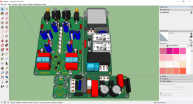
Finishing this weekend PCB before MMI design and specification:
- analog RPM meter and value
- temperature
- analog VU logarithmic meter -20dB to +3dB
- FFT displaying
- audio input selection displayed
- audio input attenuation displayed in dB
- alarms if occured
- USB interface and bootlaoder
...
JP
- asymetrical and symetrical (using THAT1200) audio inputs (software selected)
- onboard RCA and XLR or wire to board connector
- logarithmic 64 steps relay attenuator
- E-Ink display deported over wire to board connector
- IR receiver deported over wire to board connector
- encoder deported over wire to board connector
- very compact when stacked
- onboard main power filtered switch ($) or wire to board connector (VDE/UL/CE)
- onboard bridge/NTC/capacitor châssis to DC supply grounding
Finishing this weekend PCB before MMI design and specification:
- analog RPM meter and value
- temperature
- analog VU logarithmic meter -20dB to +3dB
- FFT displaying
- audio input selection displayed
- audio input attenuation displayed in dB
- alarms if occured
- USB interface and bootlaoder
...
JP
Attachments
Last edited:
JP,Only full range dB meter electronics missing (need a dual 12bits/I2C ADC for each output one for db measurement and one for FFT):
- asymetrical and symetrical (using THAT1200) audio inputs (software selected)
- onboard RCA and XLR or wire to board connector
- logarithmic 64 steps relay attenuator
- E-Ink display deported over wire to board connector
- IR receiver deported over wire to board connector
- encoder deported over wire to board connector
- very compact when stacked
- onboard main power filtered switch ($) or wire to board connector (VDE/UL/CE)
- onboard bridge/NTC/capacitor châssis to DC supply grounding
Finishing this weekend PCB before MMI design and specification:
- analog RPM meter and value
- temperature
- analog VU logarithmic meter -20dB to +3dB
- FFT displaying
- audio input selection displayed
- audio input attenuation displayed in dB
- alarms if occured
- USB interface and bootlaoder
...
JP
Aggree with Maty. I could see using this in another preamp project.
Brad
...Since we are dealing with very high frequencies when we are picking our lag compensation cap...
Because recording domain normally starts up very band pass limited and whatever we like it or not it also end up in another very band pass limited speaker domain, so what would those nano or micro seconds probably way above hearing mean when looking below domains in a comparison and think about it. Long ago X in a PM pointed me to here and is very impressed of amps distortion profile and class A features plus members companionship here but have a hard time see how compensation shall be dialed in by a human ear rather than a specific good electrical operating point as diegomj1973 and keantoken suggest.
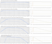
From own subjective and objective experiments over a couple of year using DSP engine with bandwidth up to 192kHz we want minimum phase behavior from system to get real foot tapping, cant tell a scientific why but can guess a personal answer is because environment around us is also bandwidth limited as a minimum phase domain. Using DSP its possible change systems phase domain relative to amplitude domain with whatever tricks one can think about would improve final reproduction but it doesn't take long to realize we change rhythm and enjoyment if phase doesn't follow amplitude response as mathematical dictated by a minimum phase domain, mathematical rules that is clear dictated looking at first two amp domain examples below where for a 1st order amplitude domain phase has rotated exactly 45º at -3dB point and for 2nd order it means exactly 90º at -3dB point.
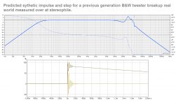
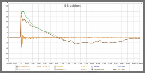
Also think will point out for digital domain haters there is real enemies when using human subjective method to dial in a HF region, who had ever looked at how a gramophone pickup or tweeter roll off up there ? as example see second attachment below how tweeter breakup can distort, third attachment below is in same analog camp in its how X's reference speakers step (square wave) should look for its measured amplitude domain curve to be right (look green trace), but in its real measured square wave is the brown one then speaker is distorting everything before 1,2mS isn't ? therefor question how can that overshoot distortion be a good base to dial in a amp compensation cap by ear without fixing speaker before this kind of use.
Hope input is of good enough use here and taken well, if you ask me amp is probably already close to a killer amp with its nice distortion profile and class A features so if system by accident end up sound clinic or disappointing look elsewhere in chain for example a documented acoustic domain as in the fifth example in 1st attachment can sound to die for.
Attachments
Last edited:
JPS,
Brilliant work, thank you very much. This gives a comprehensive monitor and control over the ALPHA, even down to relay attenuation for input level, something I've always liked since I used my first ladder resistor attenuator.
Thank you again, a wonderful addition to the ALPHA and highly adaptable to any audio system!
Hugh
Byrtt,
Thanks for your analysis. Regarding why pF and usec of delay may affect things despite bandwidth limit of ears, speakers, microphones, etc. with a continuous signal that is not discretized in time, the phase between any two points along that amplitude vs time trace can be made arbitrarily small despite bandwidth limits. That is, phase of a continuous signal can be measured with arbitrarily high resolution despite bandwidth limits. That’s how phase-sensitive lock-in amplifiers work. They have maybe 50kHz bandwidth, but when used in phase sensitive mode, they can detect very small changes in phase well beyond what their meager frequency bandwidth would suggest. So why does his matter? I think that soundstage depth and spatiality lies in the phase of the signal. If we distort this phase even at the microsecond timescales, the brain can psychoacoustically pick it up. Can our brains detect microsecond phase shifts in sound? Yes, that’s how we spatialize whether or not sound is from front back up or down with one ear via the small microsecond phase shifts imparted to the sound depending on which part of the asymmetric earlobe it traverses.
Earlobe fold is 5mm or 0.005m, speed of sound is 342m/s. Time delay of a 0.005m object is 15 microseconds. Differences between front of ear lobe vs rear of ear lobe is 1mm maybe 2mm so time delays perceptible as phase shifts are of order 3 microseconds. That’s equivalent to 300kHz yet the bandwidth of hearing is 20kHz. Bandwidth of audible sound sensitivity vs what is audible as minute phase shifts are very different.
So that’s why pF compensation can make or break an amp’s sound. Even bough we only have a bandwidth of 20kHz. The flat phase behavior out past 300kHz, is IMO, critical for an amp to have great imaging and spatiality.
Sort of related to this, in my experience after having built over 3 dozen amps, the amps with zero global feedback, despite having higher distortion, tend to have the best spatiality and 3d depth of soundstage. There is no phase lag feedback or compensation used. These amps tend to be simple 2 to 3 transistor SE Class A affairs. But those amps have the best sound stage, and it’s because they have flat phase well beyond 300KHz.
Last edited:
Hi X,
Its the calibrate by ear thing over a sometimes non documented speaker domain response and SPL level i disagree, have no problem follow to have a amp act theoretical as a short piece of copper wire, then covered band width from input to output will help and as you point out numbers as 300kHz and up is probably good numbers to save a bit on phase, but out of those dozen of amps then what about your VSSA amp which should also perform fine up there or be maybe be even more than the mentioned 300kHz bandwidth so can i ask if your conclusion for that one also kill the best spatiality and 3d depth of soundstage.
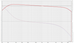
Some visual numbers is below in red trace that simulate a smooth 20Hz-20kHz speaker domain with a declining curve as frq goes up, when that isolated perfect minimum phase domain is added a 2nd order low pass up at 300kHz we get the blue trace which is just a very little bit visible in amplitude domain up above 20kHz point and move few deg in audio bands phase domain. Myself had been there with exercises for phase correction in DSP that move phase a little bit or enormous in either advance or into more lag to try to kind of correct for what a limited recording chain could be responsible of added phase distortion under recording process, and also down at low end have tried many of imagined phase corrections to clean up what transformers in old tube recording gear can be responsible for or what tens of capacitors into SS mixers can add up. Sometimes thought in those exercises aha here is something, but always down the road it turned out over time than its either track dependent or ear fatigue over time. Best results for foot tapping and a smile i had are when acoustic domain is corrected to have a real minimum phase behavior which mean whole system chain is inside loop and corrected for so it ends a same impulse/step response as its synthetic target textbook will dictate and a system amplitude response something in area or close to those JBL studies, and guess why that is so good a acoustic target curve is that more or less many pros have that one dialed in when producing our material. Now note if AKSA is right that some NFB amps is too slow in VHF phase domain that when amp sits inside loop of acoustic corrected domain we get that distortion corrected too and probably the reason why speakers as Beolap 90 and Grimmaudio LS1 using digital amplifiers don't sound as they miss anything there, if you walk into a shop and get a listen. Also real speakers bandwidth seems limit any real square wave above 6kHz area to happen and worlds probably most used source material is filtered a low pass 96dB/oct or more at 22kHz.
Its the calibrate by ear thing over a sometimes non documented speaker domain response and SPL level i disagree, have no problem follow to have a amp act theoretical as a short piece of copper wire, then covered band width from input to output will help and as you point out numbers as 300kHz and up is probably good numbers to save a bit on phase, but out of those dozen of amps then what about your VSSA amp which should also perform fine up there or be maybe be even more than the mentioned 300kHz bandwidth so can i ask if your conclusion for that one also kill the best spatiality and 3d depth of soundstage.
Some visual numbers is below in red trace that simulate a smooth 20Hz-20kHz speaker domain with a declining curve as frq goes up, when that isolated perfect minimum phase domain is added a 2nd order low pass up at 300kHz we get the blue trace which is just a very little bit visible in amplitude domain up above 20kHz point and move few deg in audio bands phase domain. Myself had been there with exercises for phase correction in DSP that move phase a little bit or enormous in either advance or into more lag to try to kind of correct for what a limited recording chain could be responsible of added phase distortion under recording process, and also down at low end have tried many of imagined phase corrections to clean up what transformers in old tube recording gear can be responsible for or what tens of capacitors into SS mixers can add up. Sometimes thought in those exercises aha here is something, but always down the road it turned out over time than its either track dependent or ear fatigue over time. Best results for foot tapping and a smile i had are when acoustic domain is corrected to have a real minimum phase behavior which mean whole system chain is inside loop and corrected for so it ends a same impulse/step response as its synthetic target textbook will dictate and a system amplitude response something in area or close to those JBL studies, and guess why that is so good a acoustic target curve is that more or less many pros have that one dialed in when producing our material. Now note if AKSA is right that some NFB amps is too slow in VHF phase domain that when amp sits inside loop of acoustic corrected domain we get that distortion corrected too and probably the reason why speakers as Beolap 90 and Grimmaudio LS1 using digital amplifiers don't sound as they miss anything there, if you walk into a shop and get a listen. Also real speakers bandwidth seems limit any real square wave above 6kHz area to happen and worlds probably most used source material is filtered a low pass 96dB/oct or more at 22kHz.
Attachments
I think combining a , less is more principle, single ended class A power amplifier with a multi-opamp-chip like that1200 is a bit funny. A transformer probably is the only credible way to go with these kind of amps. Even if the opamps in that1200 are set to run in classA all the time. Btw, are they operating class A or is a little class AB added to the Alpha (BB)?
Both amps are operating identically in modified Class A.
Let me explain. It is Class A because neither of the two output devices ever turn off.
However, both these amplifiers, and because of the Pass active CCS, as one device increases current, the other decrease - and they see-saw, one goes up 1A, the other drops 1A - they match exactly.
This means that the current total, combined both rails, has a constant current. But each rail sees rises and falls of current like a Class AB. Nonetheless, the clever aspect of this brilliant active CCS is that it almost doubles the efficiency of a Class A, and we are nudging around 30% at full power for the ALPHA20 and a little more for the BB. These are a little more efficiency of a SE Class A using a single output device with an inductive load - which is arguably the archetype of Class A, viz the SET with tubes - but the problem for the inductor is the huge cost and weight.
This is technically a wonderful amplifier because it can be made for peanuts.
Hugh
Member
Joined 2009
Paid Member
FYI - for tube folk, you may recognize the Aleph current source as equivalent to an SRPP output stage. I remember simulating it myself many years ago and found that indeed, they are equivalent in functionality
Excellent SRPP power amp of MOSFET
Excellent SRPP power amp of MOSFET
...A transformer probably is the only credible way to go with these kind of amps.
According to my informations, THAT1200 IC are better than transformers like Lundalh. Months ago I believed, wrongly, the opposite.
Tom Christiansen first and now JPS4 guessed right in the choice. Extremely low THD and very great resistance to RF/EMI too.
Last edited:
- Home
- Amplifiers
- Solid State
- Aksa Lender P-MOS Hybrid Aleph (ALPHA) Amplifier