LOLI even had some Class D amps here with a tube input stage. Still sounded rubbish.
I know. But there is a really big difference between using a gain-consuming NFB loop and simple degeneration in terms of the impact on the signal. The former is considerably more problematic. So it seems fair to me to claim no NFB if only degeneration and parasitic NFB (unavoidable) is in the circuit; we all know what "no NFB" means if we suppress our pedantry.I was just trying to clarify whether he uses feedback or not.
I find this thread interesting because some responses highlight the pervasive problem that if all you can "see" is THD then naturally you think every sonic characteristic root cause is discoverable if only you stare at the THD graph long enough.Why drag THD in? Naive applications of textbook models may be better than ignorance of textbook models, as seems to be the case for some audio designers. Better still would be intelligent thoughtful applications of textbook models.
I know. But there is a really big difference between using a gain-consuming NFB loop and simple degeneration in terms of the impact on the signal
What in the F

Isn't local degeneration gain consuming?
Or does it?What I'm looking for now is to inject some euphony or "tube magic" into it. This requires some form of imperfection, just need to find out what that is.
"Dopamine shot" is a great metaphor. I think I can empathize. I knew something was right when I was shocked by my (formerly) humble speakers making sound that I could not have believed they could ever make.Based on what people have said there seem to be different experiences of "tube magic". My experience with euphony OTL amps is more of a "something" in the sound that just makes me feel like I got a dopamine shot. Present in the entire audio range, not just the mids. Consistent across all forms of music. My very limited experience with a SET amp revealed something similar in the mid range but not quite the same kind of euphony as I'm used to. Statements I've read about SET sound seem to confirm this. In either case, finding the source of these "euphonies" is where my aim is beginning to shift.
Member
Joined 2009
Paid Member
What in the F
Isn't local degeneration gain consuming?
It's not quite so simple, people are all too focussed on talking about voltage gain and of course there is no active element that creates voltage gain - they are all transconductance devices. So the kicker is that to get voltage gain you need a current to voltage converter and the humble resistor has served us well by loading the output of the transconductance amplifier. Whether triode, tetrode, pentode, JFET, BJT, MOSFET, SIT - they are all voltage input - current output transconductance devices. The big thing with the triode is that it has considerable sensitivity to voltage input at the anode and starts to look like a 3 terminal input device whereas the other devices have very little sensitivity to the 3rd terminal and we treat them all as 2 terminal input devices (albeit with very different input impedances). For the triode it's a huge benefit, because it allows us to achieve both degeneration and voltage gain at the same node (anode), at the same time (and phase) with the simplest most reliable circuits, it is something unique. If you don't want to degenerate the anode you have to use a cascode, this takes the modulated current output from the triode and moves it to somewhere away from the anode where it can be converted to a voltage - again, with a resistor.
Last edited:
I view the degeneration at the cathode (in a common cathode configuration) as such.
When the voltage at the grid goes positive current increases making the anode swing down, (out of phase 180 degrees). This current forms a voltage across the cathode resistor, which is in phase with the grid and thus gets deducted. Remember it's the grid to cathode voltage we are concerned with. Now the the grid swings negative, the current through the triode gets reduced and the anode now swings higher (again out of phase with the grid). The reduction in current through the triode makes the voltage at the cathode swing negative (in phase with the grid voltage) which gets deducted. Again its the grid to cathode voltage we are concerned with and so if the grid is swinging negative and to so is the cathode it's the difference of the two which creates the current through the device.
So the cathode degeneration is negative feedback and thus reduces gain. Unless bypassed by a capacitor.
Last edited:
Member
Joined 2009
Paid Member
Um I don't think I agree. I view a BJT as a current controlled device where as a triode is a voltage controlled device. Am I missing something here?
If it helps to think of a BJT like that and it works for you then who's to criticize, afterall you need voltage to move current so it's not like you can have one without the other as far as most of our work is concerned. But since the so-called current gain of a BJT is non-linear and highly variable amongst devices it's best to design circuits without relying on it being well behaved.
Nevertheless, the BJT is not really a current controlled device. The physics are very clear on this, the current depends on charge density distribution as determined by applied voltages. Of course, it's a device with a rather low input impedance, think of it as a parasitic property of the device. A triode has a low input impedance too if you use the curves where Vgk is positive. All the common active devices are voltage controlled transconductance devices, no exceptions.
Wrong. You can’t have voltage without charge and movement of charge is current. Whether you decide to control the charge by voltage or current is up to what suits your circuit. You could equally call a FET current controlled if that’s how you choose to drive it.Nevertheless, the BJT is not really a current controlled device.
BJTs are called current amplifiers because collector current is set by base current. A FET is called voltage controlled because the drain current is set by the gate to source voltage. Furthermore, a BJT’s current gain can be very linear (over a range) compared with its tranconductance (never linear) or that of a FET. To imply BJTs should be considered voltage controlled because their beta is non-linear is nonsensical.
The nice thing about this forum is that many more exprience diyers here have great ideas & its nice to see the innovative spirits but at the same time there’s things that you can’t change, example 2A3 vs 2A3 of different brands or for that matter originals but off different vintage, there will always be tonal differences.
To emulate the sound of set with hybrid ss/tube seem difficult. My guru once said to me it is not feasible designing hybrids cause all the goodness from DHT will be destroy by the SS part of the circuit, this in general refers to the output stage. The other thing at hand which I believe was discuss elsewhere once is the
way we listen to music, due to our cultural differences & exposure, we listen differently. In the West, Sets was thrown out the window way back then until someone discovered why SET had such a big following especially in Japan.
Anyway it’s my 2 cents of thoughts.
Cheers
Yes there is a conundrum rooted in loudspeaker design. Change the speaker design and you can throw away SS output buffers and output transformers (unless push-pull is necessary). Moving magnet speaker, anyone?......or after more consideration maybe...
Or maybe not.
...or after more consideration maybe...Or maybe not.
Last edited:
Wrong. You can’t have voltage without charge and movement of charge is current. Whether you decide to control the charge by voltage or current is up to what suits your circuit. You could equally call a FET current controlled if that’s how you choose to drive it.
BJTs are called current amplifiers because collector current is set by base current. A FET is called voltage controlled because the drain current is set by the gate to source voltage. Furthermore, a BJT’s current gain can be very linear (over a range) compared with its tranconductance (never linear) or that of a FET. To imply BJTs should be considered voltage controlled because their beta is non-linear is nonsensical.
As far as I understand BJTs are different from mosfets in that the low impedance input was purposeful to create electron holes in between the doped areas which allow electrons to jump the gap.
Mosfets use voltage charge to form a charge "bridge" which allows electrons through.
Intrinsically BJTs need to be current driven but I think from an effective standpoint they are just low input impedance, low vbe turn-on mosfets.
A voltage is what needs to drive them and trying drive them with a current source won't end well.
If there was a true ultra low input impedance current driven transconduction device it would revolutionize the industry, but unfortunately as far as I know voltage is required to practically make an electronic switch.
I've heard this speak before. It's called purismMy guru once said to me it is not feasible designing hybrids cause all the goodness from DHT will be destroy by the SS part of the circuit, this in general refers to the output stage.
As long as you understand the traits of the parts you are using you can manipulate the results via design. If you know why a tube sounds good you can design using SS parts to keep that sound using electronic design and understanding.Also my design intention would be to make the tube amplifying stage and the output stage one in the same. There would be no separation.
Yeah, too bad ultra high impedance speakers aren't a thing. But moving coil speaker technology is the oldest and most problematic in the hierarchy of speaker technologies.Yes there is a conundrum rooted in loudspeaker design. Change the speaker design and you can throw away SS output buffers and output transformers (unless push-pull is necessary). Moving magnet speaker, anyone?...
Or maybe not.
I'll be switching to ribbons when I get the money and time.
Member
Joined 2009
Paid Member
BJTs are called current amplifiers because collector current is set by base current.
Well it's two side of the same coint, if you like to think of it as current controlled you can of course model it that way, since current and voltage will both exist. Generally though, outside of the saturation region, I always approach the device and design all my circuits with it as a voltage controlled device - through Vbe (Ebers-Moll). Of course current will flow, in fact the driving impedance must be low enough to source current to the base in order to ensure that the intended Vbe is maintained.
p.s. the beta is not only non-linear but varies between devices. The transconductance is non-linear, but it is a well behaved fundamental properly of the device with a simple and predictable relationship between collector current and gm that more or less holds for all devices.
Last edited:
Member
Joined 2009
Paid Member
Is the output transformer not an impedance matching problem?
That's how I normally look at them.
@hellokitty123 - the fact that you are near poverty suggests that you have made some poor life decisions over the years, and trying to make money from your audio tinkering is yet another one. Surely, with your purported design skills, you could land a decent paying job with an engineering firm. So it might be a good idea to get back on your feet first then do the audio design in your spare time.
All this bantering about tube sound, design topologies, SS devices, etc. is just a waste of time when you can barely put food on your table... it’s time to grow up and face the facts.
All this bantering about tube sound, design topologies, SS devices, etc. is just a waste of time when you can barely put food on your table... it’s time to grow up and face the facts.
Last edited:
Good luck with that.I always approach the device and design all my circuits with it as a voltage controlled device
We must be living in different universes. So “gm is non-linear but at least it is consistent”; good luck with that.p.s. the beta is not only non-linear but varies between devices. The transconductance is non-linear, but it is a well behaved fundamental properly of the device with a simple and predictable relationship between collector current and gm that more or less holds for all devices.
p.s. the beta is not only non-linear but varies between devices. The transconductance is non-linear, but it is a well behaved fundamental properly of the device with a simple and predictable relationship between collector current and gm that more or less holds for all devices.
1. Check 2SK1815 datasheet
2. gm depends on Hfe. Current driven bjt (high imedance seen by base) has low equivalent gm.
Member
Joined 2009
Paid Member
But the 2SK1815 isn't a bipolar transistor
Check this: https://people.eecs.berkeley.edu/~hu/Chenming-Hu_ch8.pdf
(my text books are at work so this was the best I could find)
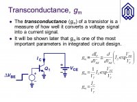
The gm is Ic / Vt.
High impedance drive of the base will mean that the input circuit may not be able to source the base current that the transistor is calling for, which means that the Vbe input voltage will 'sag'. Because of base current, because of MOSFET gat capacitance, because of triode fwd grid-cathode current - the driving circuits must be able to source current to satisfy the input impedance of the active device.
Check this: https://people.eecs.berkeley.edu/~hu/Chenming-Hu_ch8.pdf
(my text books are at work so this was the best I could find)
The gm is Ic / Vt.
High impedance drive of the base will mean that the input circuit may not be able to source the base current that the transistor is calling for, which means that the Vbe input voltage will 'sag'. Because of base current, because of MOSFET gat capacitance, because of triode fwd grid-cathode current - the driving circuits must be able to source current to satisfy the input impedance of the active device.
Attachments
Last edited:
- Status
- This old topic is closed. If you want to reopen this topic, contact a moderator using the "Report Post" button.
- Home
- Member Areas
- The Lounge
- SET sound question