If you want to see the impedance of the the feedback node you can plot V(fb)/(I(C113)+I(R113)) where V(fb) is the voltage at the base of V102. Make sure C113 and R113 have the same pin order so that one doesn't report negative current.
From that you can derive what exactly the capacitance to ground is at various frequencies and compare it with your calculations. If you want even more direct information you can plot
C=1/(2piFZ) or
1/(6.28*freq*(V(fb)/(I(C113)+I(R113))))
Which will plot a chart where the flat regions are capacitance.
Last edited:
In the previous simulations you will see that greatly altering the value of Requivalent does not have an important impact on the final results. I have tested values from 22K to several Megas and, to the conclusion that I arrived is that only Cequivalent is the most dominant parameter.
Regards
Hi Diegommj,
Thank you for running these simulations and for positing a theoretical basis for the reasons behind why tuning the compensation cap has a dramatic effect in the phase, which I believe, is directly related to how we perceive the spatial information in the signal. I will have to study and digest some more - but very good original idea here.
Cheers,
X
Good to hear from you BanglaH,
Did you ever order an Alpha 20 board? I have some left from GB2 if you are interested - I know you will enjoy it.
Thank you for asking X.
No i am not on board with GB and truly me would like a very enjoyable Amp.
With my 5 cent i was stumbling arround that idea- How i can sort out a JFet based input sektion in Pass Amps.
And it ends there, only study other circuits to understand more.
But it keeps on more darkness than lighting up for me.
All others is clearified here in much interesting thread by well educated members.
I'm sure i will build one ALPHA in any future.
Because Hugh (i would call him H2 Wizard
 ) is involved it is a must build to compare with FetZilla.
Regards
Hi Keantoken,
Thanks for your suggestion. I think you are referring to the the sim in Spice, but could this measurement be done in real life with test probes at the locations you say? I guess one would need a 4-ch O-scope...
Would one then sweep the function gen through say 5MHz and see which value of C113 gives flattest phase response?
Thanks,
X
Thanks for your suggestion. I think you are referring to the the sim in Spice, but could this measurement be done in real life with test probes at the locations you say? I guess one would need a 4-ch O-scope...
If you want to see the impedance of the the feedback node you can plot V(fb)/(I(C113)+I(R113)) where V(fb) is the voltage at the base of V102. Make sure C113 and R113 have the same pin order so that one doesn't report negative current.
Would one then sweep the function gen through say 5MHz and see which value of C113 gives flattest phase response?
Thanks,
X
Hi Diegommj,
Thank you for running these simulations and for positing a theoretical basis for the reasons behind why tuning the compensation cap has a dramatic effect in the phase, which I believe, is directly related to how we perceive the spatial information in the signal. I will have to study and digest some more - but very good original idea here.
Cheers,
X
Thanks X, I am convinced that this is the tip of the ball. It remains to associate psychoacoustics with that mode of circuit behavior (constant phase in most of the spectrum). I also think that it should not be possible to fulfill in a simultaneous and optimal way the stability criteria, constant phase of the feedback signal, a certain CLG ratio, low Johnson noise due to the feedback network components. That's where the astusia comes in.
Hi, another question please. Would it be permissible to move the mosfets off board by approx 40mm, e.g. Extend their leads by 40mm? If this is feasible would I also have to move the 220ohm resistors to keep them as close as possible to the mosfets.
I hope this is a valid question and not a stupid one.
Regards
Alan
I hope this is a valid question and not a stupid one.
Regards
Alan
Hi Alibear,
Yes you can move off-board. Use at least 18ga (16ga if you can tolerate the stiffness) stranded pure copper wire and add strain relief shrinktube to them on legs and on attachment point to PCB. Make a nice solder fillet to relieve stress risers. I don’t know if you need to move resistor. I would leave on board. Be careful with how many times you can connect and reconnect the MOSFETs to the heatsink as each time it stresses the joints mechanically, and eventually it will mechanically fail due to strain induced cracks. At least the traces won’t peel off so easily as they are tied down with lots of vias.
I have done this on the Babelfish J.
Last edited:
Hi Keantoken,
Thanks for your suggestion. I think you are referring to the the sim in Spice, but could this measurement be done in real life with test probes at the locations you say? I guess one would need a 4-ch O-scope...
Would one then sweep the function gen through say 5MHz and see which value of C113 gives flattest phase response?
Thanks,
X
It would not be necessary to perform a high frequency sweep to find an accurate value of Cequivalent and Requivalent. It would only be necessary to interpose a Rserie of important value between the output of an audio generator frequencies and the base terminal of V102, so that a high frequency value from the generator is not necessary (for the possible and concrete values to be found from Requivalent and Cequivalent).
Rserie could be a trimpot, to look for the attenuation point of the low frecuency signal of -6dB or 0.75 V RMS (point where Requivalent = Rserie). Low frecuency test may be between 50 Hz to 500 Hz aprox. Then, with the frequency value of the - 9 dB point (posibly, some point between 14 KHz to 140 KHz), we do:
Cequivalent = 1 / (2 x pi x f x 0.5 x Rserie)
And, finally, by the two resistors of the feedback network, we calculate C113 necessary.
In our example:
C113 = Cequivalent x (2k2 / 22k)
For this example, the frequency of point a - 9 dB was around 14 KHz. I do not think we need sweep frequencies beyond 140 KHz for a wide variety of cases
.Remember that in parallel to the 2K2 resistor is Requivalent, for those who wish to calculate C113 with greater precision, although I tell them that this incidence "almost does not alter the results".
C113 = Cequivalent x ((2k2 // Requivalent) / 22k)
Use audio generator with relatively low output impedance, so that the results are not significantly altered.
Regards
Attachments
Last edited:
So far it was assumed that Cequivalent does not change within a wide range of frequencies ... C113 would be valid as long as this is true. Only to verify this same would be necessary a sweep of greater frequency (possibly of up to some MHz).
But, at least, we already have tools to see the tip of this iceberg. Time, measurements and auditions will give the final verdict. This will allow to refute or accept my humble theory.
Regards
PD: Remember that in the previous post test, you must disconnect the feedback network from the base of V102, to insert Rserie between AF generator output and V102 base terminal.
Last edited:
I see two possibilities if we assume that Cequivalent is the correct explanation.
The first is that just like in Diego's simulation, the output bandwidth will be flat to a higher frequency with C113 rather than without.
The second is that Vout will have the same AC response as the base of V102, when C113 is at the right value, rather than the AC responses being different.
If either of these are not the case, then it does not look good for the Cequivalent theory.
I don't have a simulation of the most recent incarnation of this amp, so I am not playing along.
Alpha and Fullrange BLH Speaker
So I have been testing the Alpha's with my 2-way FAST speakers exclusively. My DIYA roots are in single driver fullrange speakers. I happened to have some speakers that I made 5 years ago - a flat wall mounted back loaded horn (BLH) using a TC9FD. I connected the Alpha 20 and a very wonderful, rich, full sound came out. Nice. Very nice. Both Alpha's rock with fullrange single driver speakers. This is just a lowly TC9FD, a $10 driver - but, man it is surprisingly great.
If you have a BLH, you are in for a treat with the Alpha's!
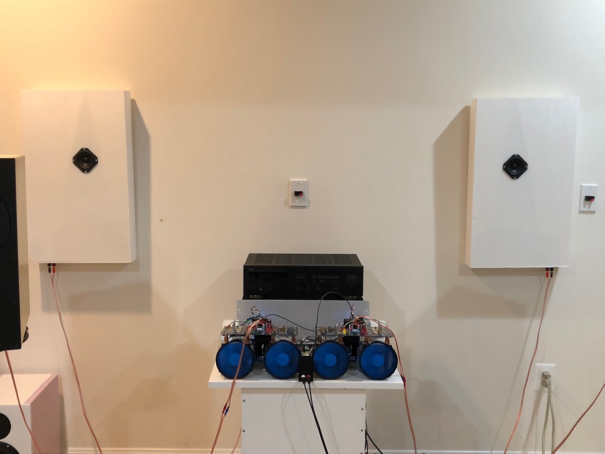
Design for BLH (actually only 3in deep, not 4in as stated in sketch):
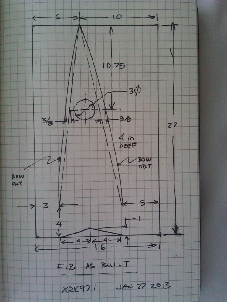
So I have been testing the Alpha's with my 2-way FAST speakers exclusively. My DIYA roots are in single driver fullrange speakers. I happened to have some speakers that I made 5 years ago - a flat wall mounted back loaded horn (BLH) using a TC9FD. I connected the Alpha 20 and a very wonderful, rich, full sound came out. Nice. Very nice. Both Alpha's rock with fullrange single driver speakers. This is just a lowly TC9FD, a $10 driver - but, man it is surprisingly great.
If you have a BLH, you are in for a treat with the Alpha's!
Design for BLH (actually only 3in deep, not 4in as stated in sketch):
Attachments
Last edited:
I don't have a simulation of the most recent incarnation of this amp, so I am not playing along.
Here they are
The original 8R version and the 4R version.
Attachments
Thanks for the simulation!
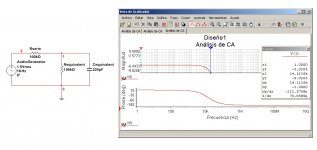
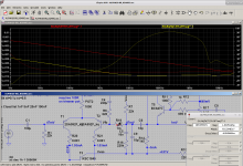
I checked out the feedback node capacitance. All the Miller path components need to be grouped together, so I just added R19 as an easy way to measure the feedback node current. The red line is the feedback node capacitance, the yellow line is the capacitance of just the transistor base. It's about 1.6pF. I used my own models just to rule out a model issue.
So the idea that the phase lead capacitor is compensating for a capacitance shunting the feedback node is untenable. It was a good use of insight and lateral thinking, but it was not to be.
Note that both C6 and C9 form the phase lead compensation. They participate nearly equally according to their ratio.
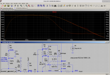
In the second image I've added a 47p+3.3k C10/R22 RC network to get rid of the resonance at 5MHz. This resonance may be interacting with the phase lead compensation and exacerbating audible effects. Who knows.
I checked out the feedback node capacitance. All the Miller path components need to be grouped together, so I just added R19 as an easy way to measure the feedback node current. The red line is the feedback node capacitance, the yellow line is the capacitance of just the transistor base. It's about 1.6pF. I used my own models just to rule out a model issue.
So the idea that the phase lead capacitor is compensating for a capacitance shunting the feedback node is untenable. It was a good use of insight and lateral thinking, but it was not to be.
Note that both C6 and C9 form the phase lead compensation. They participate nearly equally according to their ratio.
In the second image I've added a 47p+3.3k C10/R22 RC network to get rid of the resonance at 5MHz. This resonance may be interacting with the phase lead compensation and exacerbating audible effects. Who knows.
Attachments
That simulation could say something about some Alpha, the ones using those simmed mosfets. Using the Hugh recommended mosfets could already make it different, Alpha4r and BB use different mosfets again, and miss Alphas c9 but have 47/220p and pcbs between Alpha and BB differ more than just that.
- Home
- Amplifiers
- Solid State
- Aksa Lender P-MOS Hybrid Aleph (ALPHA) Amplifier