I would suggest a comparative test, with 10V at your dummy load:
-measure at amp output terminals
-measure at dummy load.
Furthermore
-measure along one cable
Measuring low distortion levels like yours might be tricky anyway.
I did that - measurement at the output terminals is practically the same, regardless of the dummy load connection - with the cable or with no cable.
The difference is only visible at the far end of the cable.
I've got no good explanation for the effect so far.
Nelson, as far i'm concerned, I use to compensate each of my speakers to reach a flat impedance from DC to 40KHz.I would recommend testing with a zobel attached at the far end of
the cable, something like .047uf in series with 5 or 10 ohms.
Including 'motional' (R,L,C in serial).
Makes miracles and simplify passive filters calculations. And the amps do not have to deal anymore with huge currents/voltages ratios differences depending on the frequency.
Some people pretend that the amps damping factor are big enough for making-it unnecessary: my ears do not agree, and the acoustic response curves/waterfalls as well.
One thing interesting is that, when you have compensated the impedance of your boomer at resonance in free air, this same network is still working in a bass reflex. Just sometimes, little adjustment of the serial resistance. I don't use closed boxes, but I believe, in this case that we have to compensate the speaker once charged.
To resume, I try to design my speakers to offer a flat acoustic response curve AND a flat impedance curve.
Last edited:
Tournesol : damping factor is usually estimated in the audio range. And cannot cure problems occuring at much higher frequencies (several tens of MHz...) because of cable inductance and capacitance. These problems can diversely affect the linearity of the final transistors, and global feedback is without effect on this sort of problems.
Nelson Pass is right (as usual !) and a good idea is to connect several Zobel networks at each strategic point of the entire system : mains, output, loudspeaker cabinet. Even 10 nF and 47 ohms can give good results. It is not uncommon that various EMR (cellular phone, computers, tablets...) can go into the amp by output cable, which is usually not shielded. Avoid wirewound resistors which becomes inductors at very high fréquencies.
Nelson Pass is right (as usual !) and a good idea is to connect several Zobel networks at each strategic point of the entire system : mains, output, loudspeaker cabinet. Even 10 nF and 47 ohms can give good results. It is not uncommon that various EMR (cellular phone, computers, tablets...) can go into the amp by output cable, which is usually not shielded. Avoid wirewound resistors which becomes inductors at very high fréquencies.
I did that - measurement at the output terminals is practically the same, regardless of the dummy load connection - with the cable or with no cable.
The difference is only visible at the far end of the cable.
I've got no good explanation for the effect so far.
I understand that the difference happens along the cable.
And it does make no difference whether or not the dummy is present.
This is an indication that your distortion in the sub-millivolt range is induced by some magnetic field along your cable acting as a loop.
So it might be an idea to connect some small pick-up coil (unshielded inductor) to your analyzer input and search for h3-field source.
Last edited:
are any of these measured differences audible?
From my perspective - not really. Amplifiers sound very good.
However, I'd like to understand the nature of the effect.
Nelson, as far i'm concerned, I use to compensate each of my speakers to reach a flat impedance from DC to 40KHz.
I was thinking about the 1 megaHertz region, and it speaks to the later
comment about distortions due to oscillation. They usually create a
lot of harmonic/IM content and aren't always visible on a scope - in fact
unexpected distortion is sometimes the clue.
That said, the grounding of the analyzer is worth looking into, particularly
when the distortion is at the load end and not the amplifier end.
A loop of some sort, with currents going where they shouldn't, could be responsible. I've seen issues with this myself and it can be quite difficult to get rid of.
This would have presented itself at the amplifiers terminals, as well as at the end of a cable though, unless additional wiring were added that could create additional loops. Sometimes you're getting an additional loop forming in a stereo pair through the second interconnect too and that's even on a shared PCB, depending on the circuit obviously.
This would have presented itself at the amplifiers terminals, as well as at the end of a cable though, unless additional wiring were added that could create additional loops. Sometimes you're getting an additional loop forming in a stereo pair through the second interconnect too and that's even on a shared PCB, depending on the circuit obviously.
Yes, I saw your values ;-)I was thinking about the 1 megaHertz region,
It was just an opportunity to share something that i found useful (for me and friends of mine).
Long thread on a similar path here- Effect of speaker cable on THD | Audiokarma Home Audio Stereo Discussion Forums
This was where we also discovered that the "non-inductive" load resistors themselves were a problem because the inner winding became a non-linear core at high frequencies.
This was where we also discovered that the "non-inductive" load resistors themselves were a problem because the inner winding became a non-linear core at high frequencies.
Thanks for looking into his Valery. I was quite suprised to see the results that I got, being a long time believer in cheap cables being nearly as good as pricey thick ones. I tried using 12ga solid copper Romex household wiring and it improved the distortion figures but still not as good as connected straight to the amp. My Class A Alpha 20 with lower global feedback had less sensitivity.
Solved ")
Ok - as Jeff mentioned earlier, that was an unwanted ground connection between the analyzer and the load return.
As soon as I have removed that ground connection - leaving only AC coupled balanced input, connected to the load - spectrums match the expectations.
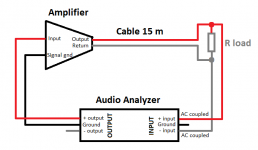
1) Connection diagram
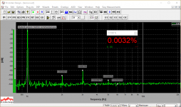
2) THD 1 KHz at the speaker terminals
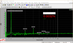
3) THD 1 KHz at the load
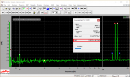
4) IMD 14+15 KHz at the speaker terminals
5) IMD 14+15 KHz at the load
Output = 10V RMS, load = 8R (always connected).
Thank you all for the discussion
It was useful - now we know the right way of connecting the analyzer
Cheers,
Valery
Ok - as Jeff mentioned earlier, that was an unwanted ground connection between the analyzer and the load return.
As soon as I have removed that ground connection - leaving only AC coupled balanced input, connected to the load - spectrums match the expectations.
1) Connection diagram
2) THD 1 KHz at the speaker terminals
3) THD 1 KHz at the load
4) IMD 14+15 KHz at the speaker terminals
5) IMD 14+15 KHz at the load
Output = 10V RMS, load = 8R (always connected).
Thank you all for the discussion
It was useful - now we know the right way of connecting the analyzer
Cheers,
Valery
Attachments

+1Ah excellent! These are the kinds of results I like
I was waiting for the cause to come to light. When measurements get a result which should not happen, it usually means that you are not measuring what you think you are measuring. Maybe the thread title could be changed to: speaker cables don't influence harmonic distortion?
Hi Valery,
Nice result! What are you using for the analyzer? Now I see that I need to make use of the differential input on my Focusrite and not just drive the + and GND connections. Did you add an AC coupling cap or is that the intrinsically AC-coupled input of your analyzer?
Thanks,
X
Nice result! What are you using for the analyzer? Now I see that I need to make use of the differential input on my Focusrite and not just drive the + and GND connections. Did you add an AC coupling cap or is that the intrinsically AC-coupled input of your analyzer?
Thanks,
X
Maybe the thread title could be changed to: speaker cables don't influence harmonic distortion?
good point.
I was waiting for the cause to come to light. When measurements get a result which should not happen, it usually means that you are not measuring what you think you are measuring. Maybe the thread title could be changed to: speaker cables don't influence harmonic distortion?
Agree - corrected the title, added the link to the right measurements to the post #1.
Hi Valery,
Nice result! What are you using for the analyzer? Now I see that I need to make use of the differential input on my Focusrite and not just drive the + and GND connections. Did you add an AC coupling cap or is that the intrinsically AC-coupled input of your analyzer?
Thanks,
X
Hi X, I've got an RTX6001 - an excellent high-precision instrument with balanced inputs and outputs - here's the link to the user manual:
https://www.rtx.dk/media/3485/rtx6001-user-manual-v07.pdf
I've got it from the group buy for a good price (although I don't think there will be another round of that group buy, at least from what I saw in the thread).
RTX has got a switch for AC/DC coupling of its inputs, so the key point is just not to use the ground connection at the input as soon as you measure at the far end of the cable.
Thank you for bringing up the point with the cables - as we see now, I had the same issue with my input connection.
Cheers,
Valery
- Status
- This old topic is closed. If you want to reopen this topic, contact a moderator using the "Report Post" button.
- Home
- Amplifiers
- Solid State
- Speaker cables don't influence harmonic distortion!