do the peaks and dips in its frequency response have a corresponding phase response?
At least sometimes they do. Whizzer cones and/or big breakup peaks seem to go with phase changes, for example:
Wharfedale Super 8
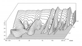
"I usually don't show nearfield measurements, but here's one. 32 ms window and 1/12 octave smoothing. It's a rare thing to view such a smooth response from 100 Hz all the way to 3 kHz. The blue is minimum phase and display the severe phase-shift at 3 kHz where all of a sudden, things starts getting out of control. The poor thing rings like a bell as can be seen below from the impulse and step response graphs."
Attachments
.....
I think this is a little misleading. Yes if you add too much damping the results are bad but in a different way. If you cause a dip where there used to be a peak, that is equally wrong.
But by definition if you had a resonance peak to begin with and you precisely correct the amplitude and phase response, "onset transients" will also be optimal.
Not really misleading at all, if you look at damping mechanism, it basically is a nonlinear mechanism which, while there are many ways you can apply it, in a cone, it is best avoid it on the cone by design. In a different thread, There was some talk about a method that uses mass at appropriate points on softer cones such as paper to tame the resonances, thus is clever since on softer cones it does not change the sensitivity yet changes the structural bending characteristic, and actually avoids damping.
I have come to dislike the term "stored energy" as it has almost no meaning in the context that it is being used - usually wrong. Sure things "store energy" that's what oscillation is all about, energy sloshing back and forth between potential and kinetic, but again its not a new concept, it's just gotten to be used as a false concept that misleads so many.
So what else do you call it? A resonance in a driver or cabinet is a delay in the transfer of kinetic energy afaik.
Also looking at some csd plots of horn speakers its possible that the reason they don't have the best csd's is because of reflections from inside the horn. So they have better acoustical coupling than the CSD suggests.
You've essentially described Fostex.
e.g. this is ~5dB more sensitive than other wideband drivers of similar size. The down side is that is has about 1/10th the Xmax, and has bigger peaks in the frequency response.
Fostex FE126En 4" Full Range
Interesting build with a fostex and ribbon, csd looks good but the off axis must be terrible.
Fostex FE126E +
A lot of full rangers seem to have good csd's low but issues up high, probably related to break up.
Interesting build with a fostex and ribbon, csd looks good but the off axis must be terrible.
I would have thought a 3.5kHz cross with a 4" would be nearly onmi, horizontally. Probably bad vertically, cos of how planars do.
As an aside - Troels 'fixed' that Fostex driver by padding the response back to 89dB and crossing it over ~an octave below the peak.
To 'fix' it a different way (and retain the sensitivity), you could load the driver into a front horn, notch out the peak, and pair it with a hefty bass box. This is the direction I like to tinker in, so I'd love to find a driver like the FE126E (with that efficiency & rising response), but with smoother FR and a better Xmax.
Basically, I want someone to buy me a unicorn.
A lot of full rangers seem to have good csd's low but issues up high, probably related to break up.
Yes. Particularly where they are really light (undamped) and efficiency is relatively high, you get the sharp peak that Troels shows (or lots of peaks).
...and the onset of break up seems to be very neatly related to the membrane size & weight. Depending on age and hearing, you may have to go to a very small full ranger before the breakup is well outside your acute hearing band.
e.g, for a series of similar nearly identical drivers:
Tymphany NE65W-04 has a 1.6g alu cone and breakup ~20kHz.
Tymphany NE85W-04 has a 2.2g alu cone and breakup ~12kHz.
Tymphany NE95W-04 has a 2.5g alu cone and breakup ~11kHz.
...and extending this series...
The Fostex 126e has a 4g paper cone and breakup ~7kHz.
Last edited:
The Fostex 126e has a 4g paper cone
NLA.
The newer FE126En which i have data handy for measures an average 2.6 g, about 0.15 g heavier once i am done with them. It is a 4.5” driver, the NE85 is a 2.5”.
dave
I see good data for the 126En here. http://www.dibirama.altervista.org/...ostex-fe126en-full-range-5-8-ohm-45-wmax.html
It looks like the break up area is a bit lower than for the old 126e, which hoses my generalisation about driver mass vs breakup
Looking at numbers...
NE65 2": 14.7 cm^2 sd, 1.7mm Xmax = 2.5cm^3 displacement.
126En 4.5": 65cmcm^2 sd, 0.35mm Xmax, = 2.3cm^3 displacement.
Half a teaspoon isn't much. It looks like either driver could manage 95dB peaks, with a 300Hz highpass.
Piston Excursion calculator
Attachments
Zu Essence Floor Standing Speakers
Funny critical review of a speaker that might have some energy storage issues along with severe lobing.
Still I'm intrigued by some of the big full rangers with a ribbon, audio nirvana has some nice drivers, basically a thin piece of paper strapped to a giant magnet. Steep crossover needed
Funny critical review of a speaker that might have some energy storage issues along with severe lobing.
Still I'm intrigued by some of the big full rangers with a ribbon, audio nirvana has some nice drivers, basically a thin piece of paper strapped to a giant magnet. Steep crossover needed
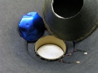
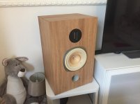
You mean like this ? (Port has been moved to the rear after the photo was taken but I don't have a good recent photo)


I need to redo my raw tweeter measurements as they appear quite a bit lumpier here than the tweeters really are, and I need to do some some proper finished result measurements as these are Vituxcad sims based on individual driver responses. But a couple of quick measurements I've taken verify the results from the sim.
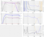
Complex crossover with multiple notches (2Khz, 4Khz) required on the FR driver as well as driver damping tweaks discussed elsewhere, and yes they are steep filters too - the electrical filters are 4th order, the acoustic response is 4th order Linkwitz Riley at 3Khz for both drivers and they phase track through most of the crossover region thanks to an all pass filter on the tweeter for delay. The purple line in in the top left graph is the L/R 4th order low pass target response, the blue line shows how close I managed to get to it.
Final result exceeded my expectations, they are extremely smooth and neutral sounding with terrific imaging. Apart from the surround dip at 1Khz which I can only partially correct with a passive crossover, they are better than +/- 2dB from 200Hz to 15Khz. Subjectively off axis response especially horizontal is very good, but I need to take measurements there to confirm my impressions. Final sensitivity after full baffle step correction is about 91dB/W/M I think, although I have no way to take an absolute measurement to confirm that. (That's based on known tweeter sensitivity of 96dB/W/M with 5dB of attenuation on the tweeter)
When I get the time to take a full set of measurements I'll probably create a thread for these detailing the crossover design, build, measurements etc but I don't have the time just at the moment to do that.
But as a general topology it can certainly work very well, but you need a very special full range driver to get good results and a lot of work with the crossover. (Notice the shape of the filter response...)
I need to redo my raw tweeter measurements as they appear quite a bit lumpier here than the tweeters really are, and I need to do some some proper finished result measurements as these are Vituxcad sims based on individual driver responses. But a couple of quick measurements I've taken verify the results from the sim.
Complex crossover with multiple notches (2Khz, 4Khz) required on the FR driver as well as driver damping tweaks discussed elsewhere, and yes they are steep filters too - the electrical filters are 4th order, the acoustic response is 4th order Linkwitz Riley at 3Khz for both drivers and they phase track through most of the crossover region thanks to an all pass filter on the tweeter for delay. The purple line in in the top left graph is the L/R 4th order low pass target response, the blue line shows how close I managed to get to it.
Final result exceeded my expectations, they are extremely smooth and neutral sounding with terrific imaging. Apart from the surround dip at 1Khz which I can only partially correct with a passive crossover, they are better than +/- 2dB from 200Hz to 15Khz. Subjectively off axis response especially horizontal is very good, but I need to take measurements there to confirm my impressions. Final sensitivity after full baffle step correction is about 91dB/W/M I think, although I have no way to take an absolute measurement to confirm that. (That's based on known tweeter sensitivity of 96dB/W/M with 5dB of attenuation on the tweeter)
When I get the time to take a full set of measurements I'll probably create a thread for these detailing the crossover design, build, measurements etc but I don't have the time just at the moment to do that.
But as a general topology it can certainly work very well, but you need a very special full range driver to get good results and a lot of work with the crossover. (Notice the shape of the filter response...)
Attachments
Last edited:
PS just read the review and details of that Zu Essence - not impressed!Zu Essence Floor Standing Speakers
Funny critical review of a speaker that might have some energy storage issues along with severe lobing.
Still I'm intrigued by some of the big full rangers with a ribbon, audio nirvana has some nice drivers, basically a thin piece of paper strapped to a giant magnet. Steep crossover needed
Lots of things about the design I don't agree with including running the FR driver without any low pass filter, (severe phasing and combining issues with the tweeter) large cone breakup resonances that are not addressed in the damping of the cone, (hard to do anything about resonances that bad in a crossover, even if it had one on the woofer, which it doesn't!) a cylinder shaped phase plug instead of bullet (huh?) a single cap for the high pass filter for a ribbon tweeter (seriously ?) and it sounds like there is no baffle step correction at all so excessive midrange and treble to the point of ear bleed.
I wouldn't enjoy listening to those...
Mine have a full 6dB baffle step correction in the crossover and even with them about 50cm out from the wall they have good solid bass down to 40Hz.
Last edited:
Damping doesn't have to be non-linear, ideally it is as linear as possible.Not really misleading at all, if you look at damping mechanism, it basically is a nonlinear mechanism which, while there are many ways you can apply it, in a cone, it is best avoid it on the cone by design.
But if you add mass to a cone you can't help but reduce the sensitivity somewhat.In a different thread, There was some talk about a method that uses mass at appropriate points on softer cones such as paper to tame the resonances, thus is clever since on softer cones it does not change the sensitivity yet changes the structural bending characteristic, and actually avoids damping.
I'm sure you've read this thread before but here is a post where I discuss the damping arrangement I've devised:
http://www.diyaudio.com/forums/multi-way/192215-phase-plug.html#post2640803
The foam strip arrangement does two things simultaneously - it applies some resistive damping to the bending waves travelling past the point where the foam is affixed, which helps dissipate some energy of the standing waves, but without having to make the surround unnecessarily thick or lossy.
However the specific pattern chosen also breaks up and "corrals" the standing waves into a desirable pattern by deliberately making the cone radially asymmetric, divided into sectors, where at a distance the radiation from the standing waves can cancel each other out, instead of the typical case with a radially symmetric driver where a given standing wave is in phase all the way around the cone and sums in the far field.
Thus you can eliminate the resonance in the far field response without necessarily having to dissipate all the mechanical energy of the resonance. (Which is not always feasible)
To explain, imagine the outer 50% diameter of the cone is broken into 8 sectors (I have 8 discrete damping strips around the outside) and at a particular radial mode resonance instead of the entire edge of the cone flapping in and out together, adjacent sectors phase alternates +-+-+-+- at this frequency where a resonance is occurring but the net summed result from these 8 sectors is zero so this resonance does not contribute to the response and thus might as well not exist. Instead the inner part of the cone where all sectors are in phase (or the whizzer cone in this case, since it is about 50% of the diameter of the main cone) is all that contributes to the output at this frequency where a resonance would have otherwise occurred.
This technique really works, and can go far beyond simply surround damping at the edge of the cone or uniform cone damping. (damar etc) I just wish I had the time and resources to develop it further beyond just the few drivers I have used it on, especially when it's nearly 15 years since I first came up with it.
Last edited:
My phone ad tablets have slowed down quite disgracefully through iOS updates, so I will have to look at the reference thread some other time on the computer. But the amount of mass used depends on the Young's modulus of the cone material. The higher the Young's modulus, the more mass and thus effects the efficiency.
Most of my efforts have been spent on metal cones because there is less unrecoverable loss. Pro audio would probably have different priorities due to the SPL needed in comparison to home environment.
For metal cones, I have patented a method to use stiffer material arranged in a way to transform radial modes into circular mode around breakup frequency, thus using the circular mode bending to stiffen the cone interactively in the radial direction to damp out resonances. At the frequencies above 10KHz, it is quite difficult to control the response precisely though, and also not so easy to produce. I have been looking into different aspects to find a more cost effective solution as well, but it is really hard.
So what else do you call it? A resonance in a driver or cabinet is a delay in the transfer of kinetic energy afaik.
Call it "resonance decay". It is not a transfer of kinetic energy. The energy is exchanged back and forth between kinetic and potential until it is all dissipated by losses such as friction or radiation.
"Ringing"
The most common name for driver energy decay or stored energy transfer (potential to Kinetic and visa versa) is "Ringing".
Many in the pro world use ringing or cone ringing to describe the effect of drivers continuing to radiate sound long after the input signal has stopped.
I believe that ringing is a far more serious issue than frequency response issues or even THD.
A key point is to separate the two very different effects or cone ringing as we are discussing here and cone FLEXING / CONE BREAKUP.
They are not the same as cone ringing... and IMO way less important as the gross time domain distortion that is cone ringing.
I have read some guys talk about the audible effects of ringing, it manifests itself as listener fatigue as the ear brain cant lock onto the sound source due to the multiple ghost echos (ringing) as the driver bounces around on its lossy / rubber suspensions.
Higher loss (stiffer) cotton / silk surrounds & stiffer spiders reduce efficiency but greatly reduce cone ringing.
My personal favourite drivers have high loss fabric surrounds, low Qts, low Mms / High Bl, high efficiency and always loaded in sealed box... NEVER delayed resonance loading with any ports / passive radiators or transmission line.
Call it "resonance decay". It is not a transfer of kinetic energy. The energy is exchanged back and forth between kinetic and potential until it is all dissipated by losses such as friction or radiation.
The most common name for driver energy decay or stored energy transfer (potential to Kinetic and visa versa) is "Ringing".
Many in the pro world use ringing or cone ringing to describe the effect of drivers continuing to radiate sound long after the input signal has stopped.
I believe that ringing is a far more serious issue than frequency response issues or even THD.
A key point is to separate the two very different effects or cone ringing as we are discussing here and cone FLEXING / CONE BREAKUP.
They are not the same as cone ringing... and IMO way less important as the gross time domain distortion that is cone ringing.
I have read some guys talk about the audible effects of ringing, it manifests itself as listener fatigue as the ear brain cant lock onto the sound source due to the multiple ghost echos (ringing) as the driver bounces around on its lossy / rubber suspensions.
Higher loss (stiffer) cotton / silk surrounds & stiffer spiders reduce efficiency but greatly reduce cone ringing.
My personal favourite drivers have high loss fabric surrounds, low Qts, low Mms / High Bl, high efficiency and always loaded in sealed box... NEVER delayed resonance loading with any ports / passive radiators or transmission line.
But ringing in the time domain and frequency response aberrations caused by a resonance are one and the same. So they have neither more or less importance - they're two manifestations of the same thing.I believe that ringing is a far more serious issue than frequency response issues or even THD.
This is what I was trying to get across back in my original long post.
But cone breakup related resonances are the main cause of ringing in cone drivers. You're making an artificial distinction that doesn't exist.A key point is to separate the two very different effects or cone ringing as we are discussing here and cone FLEXING / CONE BREAKUP.
They are not the same as cone ringing... and IMO way less important as the gross time domain distortion that is cone ringing.
The only driver resonance that isn't cone breakup related is the fundamental mass/compliance resonance that you measure with Fs/Qts etc... the other high frequency driver resonances that cause "ringing" at these higher frequencies are generally cone breakup resonances, although cavity resonances are also possible with some types of drivers like closed back ribbon tweeters.
I would say that is a fairly speculative description of what may be going on. The "echos" from the bending waves bouncing off the surround are far too close in time to be perceived as an echo. For the lowest bending mode the delay is only a single cycle. A peak in the frequency response can also cause listener fatigue, in particular at frequencies above about 2Khz and especially from 2-5Khz.I have read some guys talk about the audible effects of ringing, it manifests itself as listener fatigue as the ear brain cant lock onto the sound source due to the multiple ghost echos (ringing) as the driver bounces around on its lossy / rubber suspensions.
And since you can't have the ringing in the time domain without the peak in the frequency response, who is to say whether it is the peak in the frequency response or the ringing in the time domain that is responsible for listener fatigue when you can't have one without the other ? And why would it matter ? Just get rid of the resonance in the response!
That's a bit of a gross over simplification, there is a lot more to reducing "ringing" than the surround damping. Damping at the surround is important but overrated IMHO.Higher loss (stiffer) cotton / silk surrounds & stiffer spiders reduce efficiency but greatly reduce cone ringing.
You can't completely eliminate cone breakup resonances using only lossy edge termination at the surround as you just can't get a perfect resistive termination over a wide frequency range - there will always be a reflection that causes standing waves to form.
If damping at the surround was all that was needed then everyone would have solved the issue of cone breakup resonances long ago and I wouldn't have developed the patterned damping block approach that I did, that (at least on the drivers tested) gives far superior results than just trying to add lots of damping at the edge.
The basic problem with most cone driver breakup resonances is that the cones are radially symmetric - the same bending modes occur at the same frequencies all 360 degrees around the cone.
Last edited:
Keep saying it and I'd guess that it will sink in sooner or later.But ringing in the time domain and frequency response aberrations caused by a resonance are one and the same. So they have neither more or less importance - they're two manifestations of the same thing.
But cone breakup related resonances are the main cause of ringing in cone drivers. You're making an artificial distinction that doesn't exist.
It's more fun to have several things mean the same thing.
- Home
- Loudspeakers
- Multi-Way
- Who makes the lowest distortion speaker drivers