Danny,
Your approach increasing the shunt resistor from 820R to 2k7 while holding 22k on f2f series resistor and T1 bias 22k is correct and it is the best option.
However this changes the entire fb regime and now you need to amend the two compensation 18p caps. This has to be done empirically so I will address it in a couple of hours! These are the most critical components on the amp and if you are wrong you may blow the amp!
HD
Last edited:
Hello,
To lower the gain I added more feedback.
R7 is the feedback resistor but this one can't be changed much, because otherwise the Vout DC offset is messed up.
Lucky there's also the R6 resistor that shunts some feedback to ground.
I've changed the R6 820R to 2k7, this lowers the gain a lot:
with 820r: 0.68 Vin gives 17 Vout
with 2k7: 2.05 Vin gives 17 Vout
But in the FFT H2 and H3 were on the same level with 2k7,
but with changing the R13 ccs fb resistor to 560 I got the same nice declining H2 H3 as the original Alpha20.
So R6 2k7 and R13 560r gives lower gain with the same declining H2 H3 in FFT.
I also tried 3k9 for R6, with 3k9 there was no need to change ccs fb R13,
the FFT looked great with R13 680r
Hugh, X,
Is this lower gain version OK or did I miss something ?
In the attachments you'll find:
ALPHA20-8R_KSA992.asc the original Alpha20
ALPHA20-8R_LG1_KSA992.asc the lower gain trial with 2k7
ALPHA20-8R_LG3_KSA992.asc the lower gain trial with 3k9 (matches the FirstWatt F5 gain)
In the ltspce files the dynamic current labels are resistor bound, the Vin is set for 12Vout
Regards,
Danny
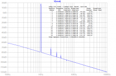
I tested your simulation with the 2k7 and it looks good. It gives about 18.4dB gain and the harmonic profile with 24vpp was dominant 2nd order and monotonically decreasing. THD was 0.004% which was extremely low, but perhaps it is the 1.93amp bias setting?
The only thing to watch for is that when increase the feedback, there may be some loss of imaging quality. The spatiality may not be as good and this can sometimes be heard as reduced soundstage depth.
From standpoint of FFT and looking at THD and profile, the lower 18.4dB gain with 2k7 R6 looks very good.
Here are the FFT's that I got and even with 1.35amp bias, THD was 0.0066% with a nice profile.
Edit, just saw Hugh's post - please wait for any changes to compensation caps to avoid catastrophe.
Attachments
Last edited:
Thanks Hugh, X for looking in this.
Looking forward for your findings.
Hugh, I'm on the other side of earth,
I'll read it next morning, night is coming now.
X, yes that unidentified thing about feedback and soundstage/imaging,
FFT says it should be better but we hear something else.
I had that experience with a DIY KT88 IT amp when I experimented with FB.
Regards,
Danny
The +12VDC power supply Smart Controller Board is isolated from the audio power supply to avoid all kind of noise generated by PWM (additionnaly to CLC filtering).
No DC detect planned!
JP
Maybe just give us a digital input pad and the software will shutdown the amp if that pin goes high. So we can attach whatever DC detect that we want. Thank you !
Thanks X, appreciate the headsup.
Looks like it works well in reality, Danny, BUT you do not have the stability issues resolved so you will need to do some listening carefully to be sure it will not be too 'hot' (too little compensation) or 'slow, ponderous' (too much compensation).
There are tricks on the spice too check it too so I will have a good look today (it's 10am here and I have eight guests in my home!).
Hugh
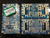
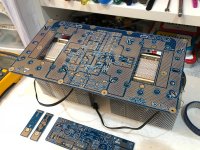
Big Boy is in the house, and boy, is he BIG!
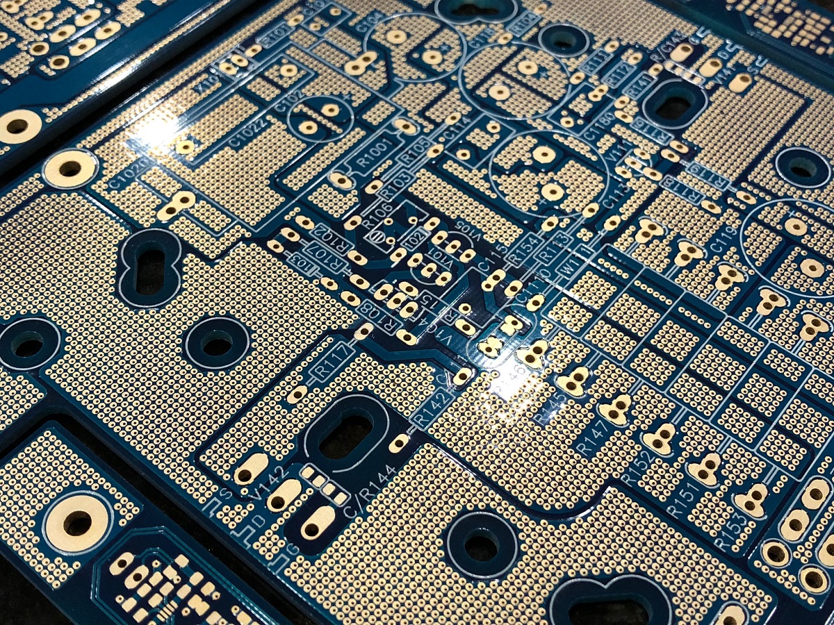
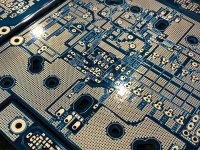
Altoids tin for size comparison. That's a lot of vias. I also realize a side benefit of lots of vias - the copper trace cannot peel off - it is literally anchored to the other side.
Nice boards JPS64! Awesone layout! EPIC in proportions!
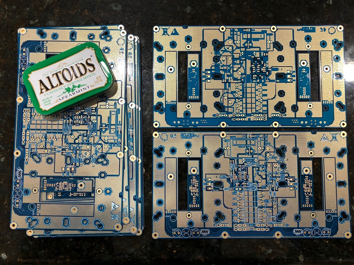
And they fit the CPU Cooler standard mounting hardware perfectly! Nice work there JPS64.")

Now that's a cool looking and cool running Class A amp!
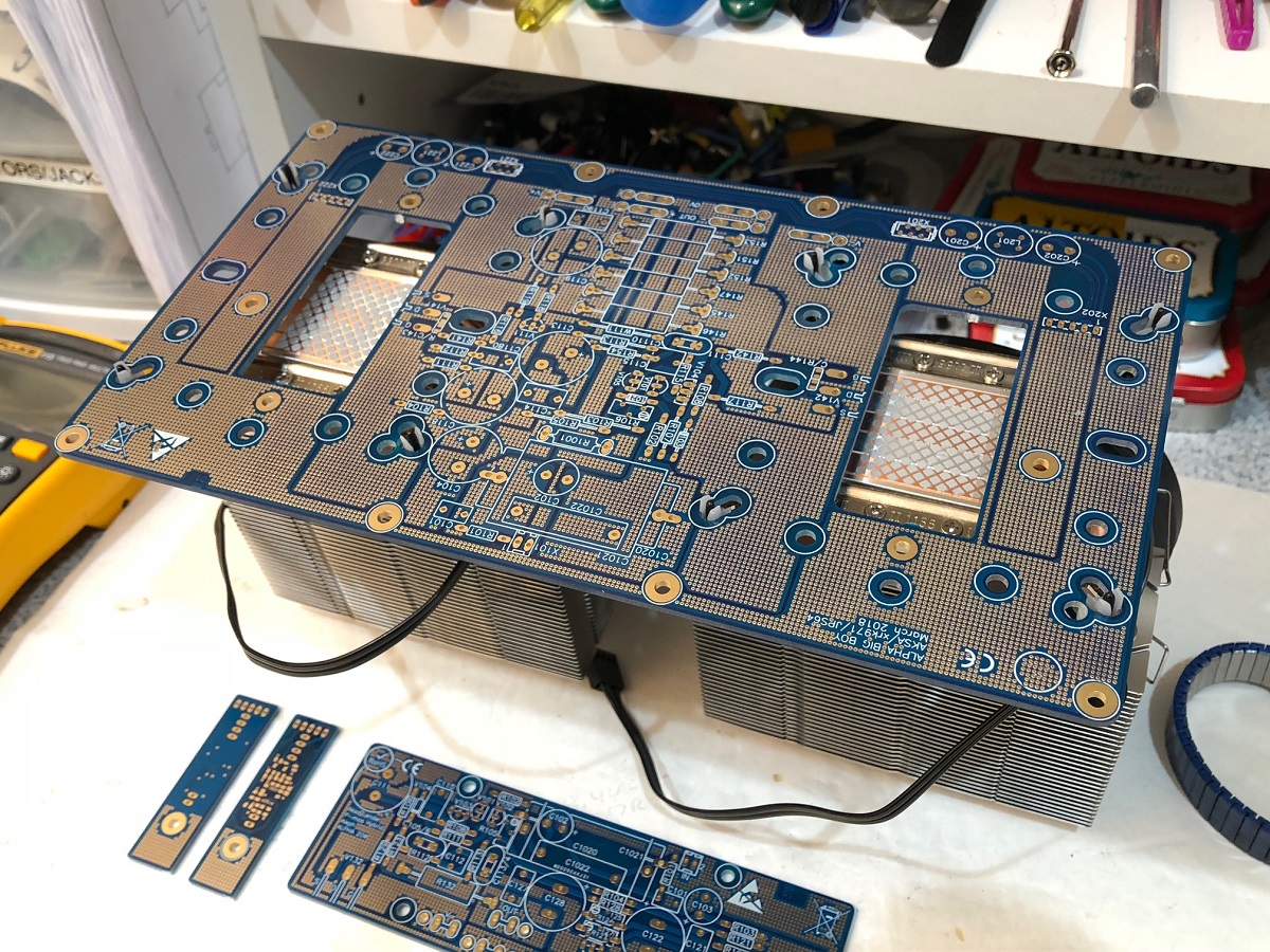
I would probably replace the plastic snap on clamp screw with a real metal bolt and metal wing-nut with a spring and washers.
Altoids tin for size comparison. That's a lot of vias. I also realize a side benefit of lots of vias - the copper trace cannot peel off - it is literally anchored to the other side.
Nice boards JPS64! Awesone layout! EPIC in proportions!
And they fit the CPU Cooler standard mounting hardware perfectly! Nice work there JPS64.
Now that's a cool looking and cool running Class A amp!
I would probably replace the plastic snap on clamp screw with a real metal bolt and metal wing-nut with a spring and washers.
Attachments

Last edited:
FINAL ALPHA 35W 4R VERSION
I have reworked the 4R ALPHA for 2.4A quiescent and 24V rails. Gain is reduced to Danny's preferred 18.2dB (9.12) and compensation has been amended at C6. All text and measurements on the simulation check out right and high pole is at 950KHz. I have reduced the fb shunt cap from 100uF to 47uF and it still gives superior bottom response due to the 2k7 shunt resistor.
LTSpice file and a gif of the working are attached. This 4R version mandates a pair of 480W mosfets; IRFP240/9240 are NOT recommended, even in triplets. I use the IRFPs in triples here on simulation because I do not have the larger mosfet models; three pairs is close to a pair of large 480W devices.
Hugh
Attachments
Last edited:
Yo X,
What are the measurements of the BB PCBs? I had plan to use two 11" x 11'' heatsinks per mono block.
Very nice PCBs,JPS64.
They are 240mm x 130mm.
I have reworked the 4R ALPHA for 2.4A quiescent and 24V rails. Gain is reduced to Danny's preferred 18.2dB (9.12) and compensation has been amended at C6. All text and measurements on the simulation check out right and high pole is at 950KHz. I have reduced the fb shunt cap from 100uF to 47uF and it still gives superior bottom response due to the 2k7 shunt resistor.
LTSpice file and a gif of the working are attached. This 4R version mandates a pair of 480W mosfets; IRFP240/9240 are NOT recommended, even in triplets. I use the IRFPs in triples here on simulation because I do not have the larger mosfet models; three pairs is close to a pair of large 480W devices.
Hugh
X,
I’m thinking I may need to order another set of boards to try both options.
Here is an option for a separate PWM fan controller with temp sensor, cheap too.
NTC 3950 Thermistor PWM Temperature Probe Speed Controller Board Control Module Buzzer DC 12V 5A CPU Fan High Temp Alarm 50k-in Integrated Circuits from Electronic Components & Supplies on Aliexpress.com | Alibaba Group
NTC 3950 Thermistor PWM Temperature Probe Speed Controller Board Control Module Buzzer DC 12V 5A CPU Fan High Temp Alarm 50k-in Integrated Circuits from Electronic Components & Supplies on Aliexpress.com | Alibaba Group
I have reworked the 4R ALPHA for 2.4A quiescent and 24V rails. Gain is reduced to Danny's preferred 18.2dB (9.12) and compensation has been amended at C6. All text and measurements on the simulation check out right and high pole is at 950KHz. I have reduced the fb shunt cap from 100uF to 47uF and it still gives superior bottom response due to the 2k7 shunt resistor.
LTSpice file and a gif of the working are attached. This 4R version mandates a pair of 480W mosfets; IRFP240/9240 are NOT recommended, even in triplets. I use the IRFPs in triples here on simulation because I do not have the larger mosfet models; three pairs is close to a pair of large 480W devices.
Hugh
Thanks Hugh !!
Lower gain and 4 ohm, that's perfect
Great that lower gain worked out very good.
I'll definitely use the newer Ixys devices, any other parameters I should look for besides the 480w ?
Mouser gives me plenty of candidates in TO264 package.
Very much appreciated for more for making this alternative version !
Regards,
Danny
AMENDED LEGEND FOR 4R ALPHA
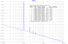
I have amended the figures to reflect 12.5W into 4R load (1.7Vpk input and 20Vpk output) and give more insight to the profile of the harmonics.
As mentioned, with loading this amplifier tends to make more H3, but even at 12.5W H3 is -88dB lower than H2 -80dB and a very good H5 output of -111dB. I believe the 8R version will sound better but this low loading for ribbon speakers should sound very good too.
I am very pleased that XRK's measurements on the proto indicates that THD/harmonics in realitiy seem to be less than these simulated figures, which is an excellent indication!
Cheers,
HD
Attachments
Last edited:
Big pcb's! Feedback now is from speakeroutput I see, like the blue schematics. Unlike earlier pcb and its white pcb schematic that has feedback connected between "big" source resistors. Is that just a difference for damping/outputimpedance ?
I think the “white” schematic is based on this schematic and the feedback topology should be the same - although Hugh will need to confirm. The schematic with the three output pairs is for the B.B. and so these recent discussions of 4ohm output impedance appears to have been run on the model for the B.B. but derated to 12W and 4ohms?
Here is original blue schematic of 20w Alpha:
Vs. the 4ohm Alpha:
The feedback topology does look slightly different (on different sides of the Aleph sense resistor).
Last edited:
- Home
- Amplifiers
- Solid State
- Aksa Lender P-MOS Hybrid Aleph (ALPHA) Amplifier