") See my last post.
See my last post.frankly , have no idea how to simulate power of
that's the thing I didn't even think of
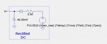
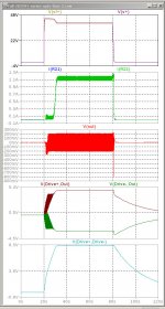
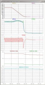
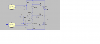
I also developed a simulation of my amplifier that shows a similar, but not identical behavior. The simulated power supplies are SPICE pulse voltage sources of the form:
PULSE({Vinitial} {Von} {Tdelay} {Trise} {Tfall} {Ton} {Tper})
In the simulation below, Tdelay=20sec, Ton=60sec, Tper=120sec. Trise and Tfall were 1.6mSec, and not important. The circuit contains a diode so that when AC power is shut off, the rail voltage decay will be determined by the current thru the circuit, not back into the transformer simulated by the voltage source. The 3.5R resistor was empirically from the measured behavior of my amplifier, shown in post #1408.
Attachments

I've not considered power off behaviour either, how serious an issue in practice do you think this is likely to be? If you have an amplifier already built then isn't it worth trying with a cheap loudspeaker?
Has there been any discussion of the shutdown circuit? I don't recall reading anything mentioning SCRs but I may have missed it.
When I turn off power to my amplifier, there is a very minor "click" in the speakers. Noticeable, but not in any way damaging to the speakers.


I don't think so. Changing the voltage at the base of the cascode transistors will not significantly alter the current through them. The input JFETs will see a different voltage at the cascode emitters but this does not change their behaviour much since they are effectively a current source into the cascode voltage source.
- Home
- Amplifiers
- Pass Labs
- F4 Beast Builders