Hello,
So i'm playing around with the TDA2822 for a portable guitar amplifier.
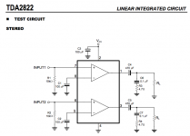
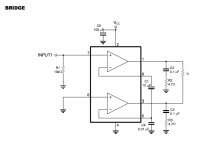
I just received the chip so last night i tried to breadboard the test circuits from datasheet just to hear it work.
I tried both the bridge and stereo (using only one input) configuration, but in both cases I got a loud high pitched noise as soon as the chip was powered. And i THINK the chip is running hot pretty fast, but i didn't dare to keep it powered for long.
As the datasheet circuit is pretty simple, I don't really see what could go wrong with this.
The only changes to the test circuit are that i added a cap in series with my input (guitar), C4 (output cap in series with pin 1) is 100uF, and R3 (resistor of the zobel network is 3.3r instead of 4.7).
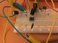
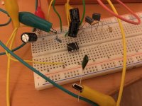
The pictures show the breadboard for the stereo circuit. theres still an unused zobel network that was used for the bridge configuration (out of curiosity, isn't it better to have one zobel network between the two drivers outputs in that case? i think i've read that before).
Could it be because it's breadboarded? too much gain (from the datasheet, the gain seems to be fixed into the chip by an internal resistor)?
Any idea would be appreciated, i'm out of idea
So i'm playing around with the TDA2822 for a portable guitar amplifier.
I just received the chip so last night i tried to breadboard the test circuits from datasheet just to hear it work.
I tried both the bridge and stereo (using only one input) configuration, but in both cases I got a loud high pitched noise as soon as the chip was powered. And i THINK the chip is running hot pretty fast, but i didn't dare to keep it powered for long.
As the datasheet circuit is pretty simple, I don't really see what could go wrong with this.
The only changes to the test circuit are that i added a cap in series with my input (guitar), C4 (output cap in series with pin 1) is 100uF, and R3 (resistor of the zobel network is 3.3r instead of 4.7).
The pictures show the breadboard for the stereo circuit. theres still an unused zobel network that was used for the bridge configuration (out of curiosity, isn't it better to have one zobel network between the two drivers outputs in that case? i think i've read that before).
Could it be because it's breadboarded? too much gain (from the datasheet, the gain seems to be fixed into the chip by an internal resistor)?
Any idea would be appreciated, i'm out of idea
Attachments
TDAs are very sensitive to layout.
My suggestion is to look into where your zobel networks terminate to the ground. Contrary to known "good practices", TDAs may work better if you move zobel components as far away from the chip as possible (within reason). You must be aware of bad ground loops and positive fb that can happen if there's a signal injection into your "ground". This can happen if you neglect good supply bypass (a 'lytic between Vcc and gnd, as close to the chip as possible), and if you connect the zobel returns in such way that they actually inject "bad fb" into your ground. This is easy to try - see if oscillation goes away when you remove the zobel. Use a couple of ten ohms dummy load during the test, like 22r or something.
My "stability test" with various TDAs is to short the + input to the ground connection, and if the circuit oscillates you most likely have a layout problem - or alternatively a bad chip.
Thanks for helping.
As an oscillating speaker is not compatible with a sleeping kid, i'll have to do tests later, but i'll already ask more questions about your answer.
I'll ground pin 6 and 5 then, and try to find a bigger supply cap.
Thanks for helping i'll try that and let you know if it's better
But it was also happening in bridged configuration with pin 5 and 6 connected so ... i guess that's not the problem here, even if it's probably a best practice to remember")
Ok so I
- paralleled 4 100uF between supply rails to get up to 400uF
- Tried to remove the zobel
- Tried to rearrange the order of the ground connections to have the ground to pin 4 and 8 close to the supply caps, and to the connection to my PSU ground, and the zobel network ground connection on the other side
- added a 100nF supply cap
aaaaand it's working!
Thanks for your help! i'm trying to bridge it now.
As an oscillating speaker is not compatible with a sleeping kid, i'll have to do tests later, but i'll already ask more questions about your answer.
- TDAs are very sensitive to layout.
Good to know, thanks! - My suggestion is to look into where your zobel networks terminate to the ground. Contrary to known "good practices", TDAs may work better if you move zobel components as far away from the chip as possible (within reason). You must be aware of bad ground loops and positive fb that can happen if there's a signal injection into your "ground". This can happen if you neglect good supply bypass (a 'lytic between Vcc and gnd, as close to the chip as possible), and if you connect the zobel returns in such way that they actually inject "bad fb" into your ground. This is easy to try - see if oscillation goes away when you remove the zobel.
How can I avoid that in such a simple circuit, in a breadboard? The way it's built now, i guess it could be possible that the supply bypass cap is not well placed since I have it on the extremity of the breadboard, then comes the connection to R1 (10k at input), then ground for pin 4 and cap of pin 8, then the extremity of the zobel network. So i guess it's entirely possible that pin 4 and 8 get some residuals from the zobel. Its actually really interesting as i never had a practical experience with ground loops before. Yay - Use a couple of ten ohms dummy load during the test, like 22r or something.
What do you mean by that? as a replacement for the speaker? then how do i know it's oscillating (i don't have a scope)? - My "stability test" with various TDAs is to short the + input to the ground connection, and if the circuit oscillates you most likely have a layout problem - or alternatively a bad chip.
All of this is already with grounded input. Bad chip is also possible, I have another one i can test, but the ground loop is definately the first suspect, i'll try that asap thanks!
Pin6 does need connecting - either via resistor to 0V or direct. Ditto pin 5 via cap. Also C3 the supply decoupling cap does need to be really close to the IC, preferably also bigger than 100uF. I'd use a minimum of 470uF myself.
I'll ground pin 6 and 5 then, and try to find a bigger supply cap.
Thanks for helping i'll try that and let you know if it's better
Pin6 does need connecting - either via resistor to 0V or direct. Ditto pin 5 via cap. Also C3 the supply decoupling cap does need to be really close to the IC, preferably also bigger than 100uF. I'd use a minimum of 470uF myself.
But it was also happening in bridged configuration with pin 5 and 6 connected so ... i guess that's not the problem here, even if it's probably a best practice to remember
Ok so I
- paralleled 4 100uF between supply rails to get up to 400uF
- Tried to remove the zobel
- Tried to rearrange the order of the ground connections to have the ground to pin 4 and 8 close to the supply caps, and to the connection to my PSU ground, and the zobel network ground connection on the other side
- added a 100nF supply cap
aaaaand it's working!
Thanks for your help! i'm trying to bridge it now.
You might have to solder this up on a piece of prototype board if you want this to work. Those plug boards have very high row-to-row capacitance. That could cause the chip to go unstable. I'd also look into proper decoupling of the chip. You'll want 100 nF from the supply pin (pin 2) to ground placed as close to the IC as you can get.
You can read my thoughts on decoupling here: LM3886 chip amp supply decoupling.
I use the LM3886, but the concept of decoupling applies just as much in your case.
Do you have an oscilloscope so we can take a look at the output?
Tom
You can read my thoughts on decoupling here: LM3886 chip amp supply decoupling.
I use the LM3886, but the concept of decoupling applies just as much in your case.
Do you have an oscilloscope so we can take a look at the output?
Tom
Last edited:
You might have to solder this up on a piece of prototype board if you want this to work. Those plug boards have very high row-to-row capacitance. That could cause the chip to go unstable. I'd also look into proper decoupling of the chip. You'll want 100 nF from the supply pin (pin 2) to ground placed as close to the IC as you can get.
You can read my thoughts on decoupling here: LM3886 chip amp supply decoupling.
I use the LM3886, but the concept of decoupling applies just as much in your case.
Do you have an oscilloscope so we can take a look at the output?
Tom
Thanks for helping!
I actually already added 100nF between the supply rows near pin 2, that's good practice anyway so, that's done.
Sadly, i don't have an oscilloscope (if you know something cheap that can be used for low frequency and audio, i might be interested
). I'll read your page about supply decoupling, i'm always glad to find a goos source of information like your page, thanks!
Thanks for helping!
I actually already added 100nF between the supply rows near pin 2, that's good practice anyway so, that's done.
Sadly, i don't have an oscilloscope (if you know something cheap that can be used for low frequency and audio, i might be interested
I'll read your page about supply decoupling, i'm always glad to find a goos source of information like your page, thanks!
So i'm reading your page on power decoupling and grounding (it's extremely interesting, thanks for this!) and i'm surprised because actually, after some more tests, my oscillation actually dissapears when the ground from the speaker is connected to the ground rail of the breadboard. Originally, i connected it to the ground of the PSU, trying to star ground it and to avoid polluting the ground on the breadboard.
Why do you think it was a bad idea here?
Sadly, i don't have an oscilloscope (if you know something cheap that can be used for low frequency and audio, i might be interested
I am short of a storage oscilloscope and a simple (imprecise) THD analyser.
So, I use a laptop with a sound-card (internal/external) and have downloaded the program "Soundcard Oscilloscope". It is not as good as a real oscilloscope (bandwitdh to 20KHz) but for audio it gives you an idea about what is going on.
By operating it from the battery, you avoid many grounding problems.
Last edited:
This is a single-ended app, where power-rails are intrinsically inter-connected and mixed with audio-ground. A little different rules apply here compared to a dual-rail power-amp, where you can decouple power and signal ground more gracefully!
With single-ended amps; IC-amps in particular, my rule no.1 was to religiously ground-reference everything to the "-" power-pin(s) of the chip. This pin (or pin-group) should be your local gnd star-point, alternatively the star-point could be also the "-" pad of your IC decoupling cap, whichever works better in your app. hth.
IIRC, ST appnotes and datasheets for TDA chips include factory-recommended pcb layouts. Study these and as tomchr pointed out, try to prototype on some kind of a perfoboard.
Last edited:
Sadly, i don't have an oscilloscope (if you know something cheap that can be used for low frequency and audio, i might be interested
I am short of a storage oscilloscope and a simple (imprecise) THD analyser.
So, I use a laptop with a sound-card (internal/external) and have downloaded the program "Soundcard Oscilloscope". It is not as good as a real oscilloscope (bandwitdh to 20KHz) but for audio it gives you an idea about what is going on.
By operating it from the battery, you avoid many grounding problems.
This is a single-ended app, where power-rails are intrinsically inter-connected and mixed with audio-ground. A little different rules apply here compared to a dual-rail power-amp, where you can decouple power and signal ground more gracefully!
With single-ended amps; IC-amps in particular, my rule no.1 was to religiously ground-reference everything to the "-" power-pin(s) of the chip. This pin (or pin-group) should be your local gnd star-point, alternatively the star-point could be also the "-" pad of your IC decoupling cap, whichever works better in your app. hth.
IIRC, ST appnotes and datasheets for TDA chips include factory-recommended pcb layouts. Study these and as tomchr pointed out, try to prototype on some kind of a perfoboard.
Well i guess that was it! using the ground of the IC as a reference for the speaker solved my problem.
I am short of a storage oscilloscope and a simple (imprecise) THD analyser.
So, I use a laptop with a sound-card (internal/external) and have downloaded the program "Soundcard Oscilloscope". It is not as good as a real oscilloscope (bandwitdh to 20KHz) but for audio it gives you an idea about what is going on.
By operating it from the battery, you avoid many grounding problems.
Thanks! trying to install this now
Ok, so now i'm trying the bridged version and i have another problem that i never experienced before.
With no input signal I don't have oscillation anymore, everything seems fine.
When i touch my guitar, as soon as some audio signal goes into the circuit, it kindof shorts out. My PSU light goes off, the HP make a light 'thud' noise, then the power comes back, and it happens every second or so.
If i try to increase the volume of the input signal the frequency of this power loss increases.
What could be the cause of this? not enough current draw on my PSU?
Ok so i just tried to use a 9v, 500mA PSU to power this and it's still happening so i guess it's not lack of amperage.. this small chip wouldn't draw more than 500mA would it?
Last edited:
spec sheet states 1.5 amp peak @ 15 VDC.
so yeah, current is insufficient especially with 9 v and only a half an ampere.
Great! So it’s absolutely not the answer that I wanted to hear but at least I understand what’s wrong
Ok so let me ask the question in another way then. I want this project to be 9v battery powered, which chip (or transistor) should I use to get 1-2watts out of it , into 8 or 4 ohms. and a battery that last at least a couple of hours.
I tried lm386 obviously but The headroom is awful, it’s unstable, and it sounds tiny. Which is why I moved on to this chip.
Is there an answer to the 9v battery constraint with better specs than the lm386?
If not, how could it get out of this current limitation? More batteries of smaller voltage in series? A kind of rechargeable cell?
Thanks a lot for you advices
For maximum battery life, you'd need to ditch anything classAB and move on to classD. Plenty of classD amps work fine on a 9V battery.
Do you want merely better specs or more satisfying sound?
I’m looking for a better sound, to me the lm386 sounded trebly, saturated way too quickly, and was not stable enough, with still less volume than I’d want.
Are there some class D chip Amp? Or am I looking at something completely different to implement? would you have some references? Chip names? I could look up? I definately have no problem about icing to class D, if that solves the problem.
I suggest that, rather than look for the chip, buy yourself a chip already implemented on a board. ClassD chips are often difficult to solder DIY with close together pins.
PAM8610 looks to have the right operating voltage range for what you want : PAM8610????? 2x15W??? ??? ?????? ??-???
PAM8610 looks to have the right operating voltage range for what you want : PAM8610????? 2x15W??? ??? ?????? ??-???
I suggest that, rather than look for the chip, buy yourself a chip already implemented on a board. ClassD chips are often difficult to solder DIY with close together pins.
PAM8610 looks to have the right operating voltage range for what you want : PAM8610????? 2x15W??? ??? ?????? ??-???
Thanks for the link. I bought one to test this solution, even if i would prefer a more "diy" solution
. We'll see in 50 days when it arrives.If anyone else has another solution in mind, i'd be curious to hear it too.
- Status
- This old topic is closed. If you want to reopen this topic, contact a moderator using the "Report Post" button.
- Home
- Amplifiers
- Chip Amps
- Oscillating TDA2822? why?