Hi Cal, I had a bit of spare time so I have done something of a worked example using your chosen drivers. I have used Virtuix cad as it is much easier to do all the manipulations that are needed to do a simulation from manufacturers data. (its also free, see the software tools section of this forum for more info Software)
The stages here are input TS parameters (fortunately the DS100 was already present but I had to add the ES170).
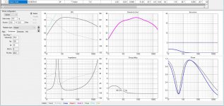
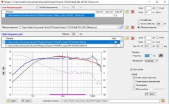
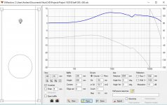
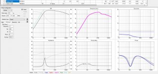
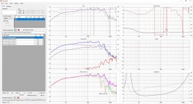
Calculate boxes sizes - I went for a simple Q 0.577 closed box for the bass this came out at 19L which is reasonable for a three way. Export this data SPL and impedance. I also simulated the box and calculated the diffraction at this point (you could do it later) and selected it so you can see an approximate Bass response with baffle step loss.
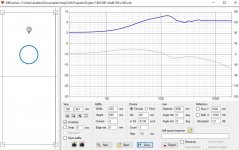
For the mid range I went for a Butterworth Q0.707 response as it keeps the mid enclosure small without to much peaking due to the box. The mid enclosure cam out to 1.7L which should not make the overall enclosure much larger. (its not good for the mid to share with the bass driver the pressure from the bass driver could cause the mid to behave in odd ways. I also calculated the effect of the baffle on this driver at this time. export of SPL and impedance again.
Next the driver responses need to be merged so I merged the bass simulation with the baffle simulation selected with the bass drivers frequency responses. An exported for all Reponses on and off axis.
Did the same for the midrange responses DS100.
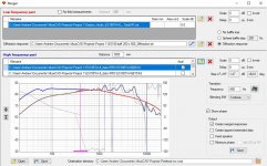
Simulated the tweeter diffraction and noted there is some lift in the 1-2Khz region which might affect the crossover especially the phase of the roll off. I then merged these responses as well (but only up to 2K as I had to merge the on axis with the off axis to make this work and they diverge at this frequency (with more time it could be done individually but it doesn't add much value as there is nothing you can do about the high frequency diffraction in the crossover you need to smooth the edges of the cabinet or move the tweeter to do this) I did a diffraction sim in a box with sharp edges so you can see why you want rounded ones.
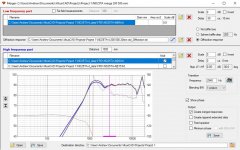
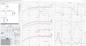
Now I have all my speaker responses with the simulated boxes and the baffle effects added. I mow load each of these into the speaker response boxes on the simulator and upload the simulated impedance responses for the different boxes. (the tweeter impedance is unmodified)
At this point I have added your crossover with some resistance added for the inductors (the more you pay the lower this is I have use 0.5 ohms for all of them as a starting point)
You can see the response you will probably get its not great and as pointed out the baffle step loss will make it sound very bass light. This is the danger of using manufacturers data without simulating the box (and even if you do the simulation of the box reality might not match perfectly -the distance from the wall will make a big difference tot eh bottom end)
I will see if I can do an optimisation next.
You are welcome to these files if you want to have a play I can zip them up and send them to you if you PM me an email address.
The stages here are input TS parameters (fortunately the DS100 was already present but I had to add the ES170).
Calculate boxes sizes - I went for a simple Q 0.577 closed box for the bass this came out at 19L which is reasonable for a three way. Export this data SPL and impedance. I also simulated the box and calculated the diffraction at this point (you could do it later) and selected it so you can see an approximate Bass response with baffle step loss.
For the mid range I went for a Butterworth Q0.707 response as it keeps the mid enclosure small without to much peaking due to the box. The mid enclosure cam out to 1.7L which should not make the overall enclosure much larger. (its not good for the mid to share with the bass driver the pressure from the bass driver could cause the mid to behave in odd ways. I also calculated the effect of the baffle on this driver at this time. export of SPL and impedance again.
Next the driver responses need to be merged so I merged the bass simulation with the baffle simulation selected with the bass drivers frequency responses. An exported for all Reponses on and off axis.
Did the same for the midrange responses DS100.
Simulated the tweeter diffraction and noted there is some lift in the 1-2Khz region which might affect the crossover especially the phase of the roll off. I then merged these responses as well (but only up to 2K as I had to merge the on axis with the off axis to make this work and they diverge at this frequency (with more time it could be done individually but it doesn't add much value as there is nothing you can do about the high frequency diffraction in the crossover you need to smooth the edges of the cabinet or move the tweeter to do this) I did a diffraction sim in a box with sharp edges so you can see why you want rounded ones.
Now I have all my speaker responses with the simulated boxes and the baffle effects added. I mow load each of these into the speaker response boxes on the simulator and upload the simulated impedance responses for the different boxes. (the tweeter impedance is unmodified)
At this point I have added your crossover with some resistance added for the inductors (the more you pay the lower this is I have use 0.5 ohms for all of them as a starting point)
You can see the response you will probably get its not great and as pointed out the baffle step loss will make it sound very bass light. This is the danger of using manufacturers data without simulating the box (and even if you do the simulation of the box reality might not match perfectly -the distance from the wall will make a big difference tot eh bottom end)
I will see if I can do an optimisation next.
You are welcome to these files if you want to have a play I can zip them up and send them to you if you PM me an email address.
Attachments
-
 ES180 19L 200 500 baff.JPG205.1 KB · Views: 114
 -
 ND25TA-4 200 500 20mm merge.JPG135 KB · Views: 35
 -
 ND25TA-4 200 500 20mm rad.JPG113.7 KB · Views: 33
 -
 ND25TA baff 200 500 sharp.JPG113.2 KB · Views: 33
 -
 RS100 baff 200 500 1.7L box.JPG132.3 KB · Views: 34
 -
 ES180 merge LF sim baff 200 500 HF data.JPG131 KB · Views: 118
 -
 RS100-4 baff 200 500.JPG110.1 KB · Views: 121
 -
 ES180 baff 200 500.JPG115.4 KB · Views: 116
 -
 RS100-4 1.7L 200 500.JPG198.6 KB · Views: 118
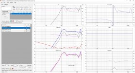
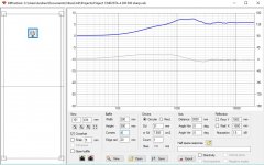
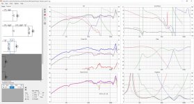
In the next image I have added simulation for the driver physical offsets. This assumes they are on a flat baffle. I have used typical values for the types of drivers you have used as you cannot know the exact delay due to offset without measuring the drivers.
I have assumed the mid range is about 60uS 2cm 4/5inch behind the tweeter and the woofer is 90us appr0x 3cm 1 3/8 inch behind (measurement values are extremely rough approximations the time is exact). You should be able to see a shift in the relative phase of the Drivers.
I have assumed the mid range is about 60uS 2cm 4/5inch behind the tweeter and the woofer is 90us appr0x 3cm 1 3/8 inch behind (measurement values are extremely rough approximations the time is exact). You should be able to see a shift in the relative phase of the Drivers.
Attachments
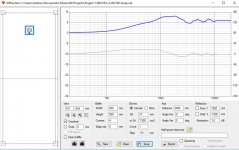
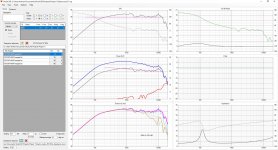
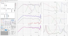
This is the optimised solution. What this tells me is, the box solution I used for the bass driver was poor the sensitivity is low. A ported solution might work better.
The mid range has an awkward response as it has a peak / dip in an awkward location to equalise out. I also had to invert it to get the phase to work out.
The tweeter does not really play low enough flat enough to be a good driver to cross over into this mid range. It will work but its response is awkward to correct on of the Peerless ring radiators with their low resonance would be much easier.
The mid crossed to the tweet at 3K give a fairly good off axis power response with the limited of axis data available.
Phase has worked out OK but its no great however I was aware of the large number of components the crossover was using and didn't want to expand it any further.
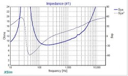
The impedance response has worked out OK, however it would have been much easier to ensure this did not cause amp problems if 8 Ohm drivers had been selected. The Low frequency low pass is a bit reactive and might cause power problems with the amp - you can see there is some bass gain in this area.
The mid range has an awkward response as it has a peak / dip in an awkward location to equalise out. I also had to invert it to get the phase to work out.
The tweeter does not really play low enough flat enough to be a good driver to cross over into this mid range. It will work but its response is awkward to correct on of the Peerless ring radiators with their low resonance would be much easier.
The mid crossed to the tweet at 3K give a fairly good off axis power response with the limited of axis data available.
Phase has worked out OK but its no great however I was aware of the large number of components the crossover was using and didn't want to expand it any further.
The impedance response has worked out OK, however it would have been much easier to ensure this did not cause amp problems if 8 Ohm drivers had been selected. The Low frequency low pass is a bit reactive and might cause power problems with the amp - you can see there is some bass gain in this area.
Attachments
Thank you everyone for your replies. They are very much appreciated ")
@gfiandy,
What can I say... the time and effort you have put into this is boggling. It appears to be a comprehensive evaluation of the chosen drivers, modeled in a guesstimate box enclosure. Thank you for the dedicated response.
I'll need some time (a lot) to digest this info and try to learn from your method. Let's hope I'm up to it.
Here are some of the missing details that you kindly worked around;
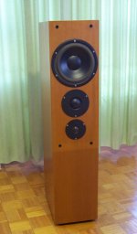
The plan is for a rear vented enclosure, 29 litres total (24 + 5). Based loosely on Jim Holtz's Statement Monitors and incorporating the mid PVC chamber he used on another build, the Finalists.
The baffle config will be a TMW centre aligned forced by the construction method open to me, and likely tapered to all 4 corners (30 deg?), leaving a minimal flat centre section to accomodate the drivers.
As of this point in time the only confirmed driver is the ES180TiA. The mid and tweeter combination I listed earlier, in my mind, were the best available combination I could buy locally. It looks as though they were not as ideal and are troublesome in this configuration. It looks as though I might be better to look at alternatives for both and buy elsewhere.
Overall my objective was to build a descent set of mains that could be used with a tube amp nearfield but not limited by their power handling. Not expecting a pair of "party rockers" mind but did want a degree of flexibility should my present circumstances change. At a minimum and should this be the case, I would be fine with re-working the crossover if need be as long as the drivers used were up to it.
Hope the additional info is useful.
Many thanks again to all.
Dennis
@gfiandy,
What can I say... the time and effort you have put into this is boggling. It appears to be a comprehensive evaluation of the chosen drivers, modeled in a guesstimate box enclosure. Thank you for the dedicated response.
I'll need some time (a lot) to digest this info and try to learn from your method. Let's hope I'm up to it.
Here are some of the missing details that you kindly worked around;
The plan is for a rear vented enclosure, 29 litres total (24 + 5). Based loosely on Jim Holtz's Statement Monitors and incorporating the mid PVC chamber he used on another build, the Finalists.
The baffle config will be a TMW centre aligned forced by the construction method open to me, and likely tapered to all 4 corners (30 deg?), leaving a minimal flat centre section to accomodate the drivers.
As of this point in time the only confirmed driver is the ES180TiA. The mid and tweeter combination I listed earlier, in my mind, were the best available combination I could buy locally. It looks as though they were not as ideal and are troublesome in this configuration. It looks as though I might be better to look at alternatives for both and buy elsewhere.
Overall my objective was to build a descent set of mains that could be used with a tube amp nearfield but not limited by their power handling. Not expecting a pair of "party rockers" mind but did want a degree of flexibility should my present circumstances change. At a minimum and should this be the case, I would be fine with re-working the crossover if need be as long as the drivers used were up to it.
Hope the additional info is useful.
Many thanks again to all.
Dennis
Thanks for the update. Tube amps like a very smooth impedance response to work well they also work better with higher impedance drive units. You might want to use a conjugate load to flatten the bass resonance, the mid and tweet should be filtered out at resonance. The tweeter might need a zobel.
What is the power of the tube amp as you might need higher sensitivity drivers if its a small amplifier?
Do you know the tube amps output impedance?
Porting should help a lot with the low frequency sensitivity so it shoukd be possible to keep the bass driver.
What is the power of the tube amp as you might need higher sensitivity drivers if its a small amplifier?
Do you know the tube amps output impedance?
Porting should help a lot with the low frequency sensitivity so it shoukd be possible to keep the bass driver.
Hi Dennis, If it were me, I'd build this properly once and for all, meaning a Dayton Audio RS 52 AN-8 for a midrange. This will give you really good overall power response and you can cross it higher without compromising SQ. Search for a Dynaudio Compound 3 loudspeaker that may serve as an example. Mine are just a variation on the same theme with better bass performance.
Attachments
Thanks for the update. Tube amps like a very smooth impedance response to work well they also work better with higher impedance drive units. You might want to use a conjugate load to flatten the bass resonance, the mid and tweet should be filtered out at resonance. The tweeter might need a zobel.
What is the power of the tube amp as you might need higher sensitivity drivers if its a small amplifier?
Do you know the tube amps output impedance?
Porting should help a lot with the low frequency sensitivity so it should be possible to keep the bass driver.
So you agree the resonant peak of the ES180TiA needs taming to flat for use with the tube amp? (not an issue with ss amp as I understand)
The mid & tweet are givens if the bass peak is attended to...
It is only a small se... 7w? It has both 4 & 8 out taps.
At any rate, I don't have much invested in the tube amp. I also have a ss amp (Luxman 505X) if it better suited.
cheers
Hi Dennis, If it were me, I'd build this properly once and for all, meaning a Dayton Audio RS 52 AN-8 for a midrange. This will give you really good overall power response and you can cross it higher without compromising SQ. Search for a Dynaudio Compound 3 loudspeaker that may serve as an example. Mine are just a variation on the same theme with better bass performance.
Hi Lojzek, thanks for your input.
I just looked at the RS52AN-8... response looks much better!
Will check out the Dynaudio Compound 3 also. Thank you!
Question: With the RS52 could you recommend a suitable tweeter... my preference is mainly for "air"... clean but certainly not overbearing.
cheers
A suitable tweeter could be a lot of the higher quality units, Seas, Scan Speak, etc. but my choice would fall on Morel CAT 308. They also carry spare voice coil assemblies and not overcharging for these, which is always nice to have around just in case.
On first looks the Morel seems to outclass anything I can buy locally at double the cost
SB Acoustics has very reasonably priced units and worthy.
Not saying SB are not good, but look here... A$ of course
I've built solid state amps with high output impedance and valve amps with low. Your design may or may not require this impedance work.(not an issue with ss amp as I understand)
I've built solid state amps with high output impedance and valve amps with low. Your design may or may not require this impedance work.
Hi Allen,
Thanks for chiming in on this.
You no doubt noticed the quote 2 pages back from forum member SpeakerDave where you also commented at that time. My interest mainly is with the OP's findings here where as I understand he implemented the notch and found it to be beneficial. Of course safety of operation is another prerequisite.
I'm heartened by the fact that you suggest this may not be required in my case, but as I'm prepared to implement the fix if it is needed anyway, I'd firstly like to know how, if at all, leaving the peak may impact bass reproduction... and would any impact be amp dependent?
cheers
This link is a description of how valve amps and solid state can differ. As noted a good valve amp can have a output impedance close to that of a solid state amplifier. However depending on the design it can also have a quite high impedance and behave almost like a current source.
Valve Amps: Valve verses Solid-state amps
Valve Amps: Valve verses Solid-state amps
This link is a description of how valve amps and solid state can differ. As noted a good valve amp can have a output impedance close to that of a solid state amplifier. However depending on the design it can also have a quite high impedance and behave almost like a current source.
Valve Amps: Valve verses Solid-state amps
Thanks for the link.
So if I got this the right way around, speakers with impedance peaks at either end of the freq spectrum actually benefit from use with a tube amp via the increase in power delivered. (if I'm correct here, this is a driver seemingly dampening itself?) If correct, then the first question I have is how much is too much? If there is an ideal peak amplitude does this equate to a better sounding bass for instance?
To explain my point further, the primary concern is that the frequency response will be altered by interaction with the output impedance. This is amp dependent, but not necessarily the type of amp. I always choose amplifier type, and output impedance independently.I'm heartened by the fact that you suggest this may not be required in my case, but as I'm prepared to implement the fix if it is needed anyway, I'd firstly like to know how, if at all, leaving the peak may impact bass reproduction... and would any impact be amp dependent?
A secondary, and much lesser concern is that even with a low output impedance a reactive load may put unnecessary signals back through a feedback loop with unexpected results. I have noticed small improvements in conjugating amplifier loads (speakers) with low output impedance amps in a small number of cases. Often it isn't an issue.
I do it with my speakers as a matter of course whether they need it or not, particularly in the midrange. In the case of a bass impedance peak driven from a higher output impedance, the system Q will change from when it was set with the box volume. This is what it is, or in other words, you could design this way if you wanted rather than to flatten the impedance. Most probably wouldn't go that way unless they were sure of the outcome in the first place.
Safety, what is your concern? If too high an impedance is used with a valve amp sometimes the Voltage around an output transformer could be higher than it was designed for. Normally this means don't run it without a load. Even this is not always a problem and I wouldn't worry too much with a speaker connected unless the amp was particularly troublesome. With regard to (very) high frequency anomalies it should be the responsibility of the amp to have the impedance covered.
On first looks the Morel seems to outclass anything I can buy locally at double the cost
You think you have problems with a local supply?
A secondary, and much lesser concern is that even with a low output impedance a reactive load may put unnecessary signals back through a feedback loop with unexpected results.
This is important. There are common measures taken, such as an LR on the output of the amplifier to make it have high output impedance at high (unwanted) frequencies. Otherwise, the amplifier should be designed to handle these reflections.
I've always disliked how class D amplifiers sound. There are good ones, but they don't compete with other class A or AB amplifiers. I'm sure it's because the output filter interacts with the speaker crossover. Anyway, any reactance on the output of an amplifier can certainly interfere.
I don't think this project has an amplifier sister project where the impedance of the amplifier and speaker are all integrated in one design. The rule of thumb is to try to get a decent flat speaker impedance response, and to ensure your speaker's phase variations aren't too bad (what too bad is, I can't say for sure).
- Status
- This old topic is closed. If you want to reopen this topic, contact a moderator using the "Report Post" button.
- Home
- Loudspeakers
- Multi-Way
- 3 Way Crossover - a first attempt