yes, I said that they did. But not all. But not placed there to add clarity to the sound. Added to protect the amp. However, if we are still interested in talking about SOTA preamps and PA, neither will use coupling caps and do as JC said... provide protection circuit in event of failure rather than mess with the sound. A 'high-end' ss preamp and PA would use servo on preamp out and on PA out.
THx-RNMarsh
So no tube and tube/SS hybrid pre amps are SOTA?
This thread often appears to run in a reality isolation zone.
")
T
One problem with devices that short the output to ground is that they usually guarantee the outputs short, the PCB's burn open and the device itself turns into a fancy looking piece of wire. You could say they are effective at saving the load unless it already died and is the cause of the protection action. Mutually Assured Destruction on a little scale.
Relays seem to be the least of the evils out there, except for maybe a mosfet relay replacement I saw a few months ago. I haven't a problem with replacing my relays every so often. Consider it maintenance - like replacing your tires only cheaper.
-Chris
Relays seem to be the least of the evils out there, except for maybe a mosfet relay replacement I saw a few months ago. I haven't a problem with replacing my relays every so often. Consider it maintenance - like replacing your tires only cheaper.
-Chris
Even the auto industry isn't immune to relay issues.
Safety Recall 15S39 – Headlights Inoperative – 2003-2005 Ford Crown Victoria & Mercury Grand Marquis | Ford - Part 9
I replaced the offending relay in my Crown Vic a couple of years ago, but am considering taking the car in to get the module changed any way.
Safety Recall 15S39 – Headlights Inoperative – 2003-2005 Ford Crown Victoria & Mercury Grand Marquis | Ford - Part 9
I replaced the offending relay in my Crown Vic a couple of years ago, but am considering taking the car in to get the module changed any way.
The biggest issue with relays is not turning the volume down before turning the power off on receivers or power amps and not waiting until the relay has clicked on before turning the volume up. The power switch is just turned off or on.
This means the relay is opening or closing under load which pits the contacts, and leads to the eventual relay failure. Simply turning the volume down before turning it off and waiting to turn it up until the relay has clicked on when starting a listening session will extend the life of the relay and reduce the distortion it can cause from contact pitting.
It’s this long term degradation over 100s of cycles of this domestic abuse
that damages the contacts, rather than the ocassional use as a protective device
Last edited:
Even the auto industry isn't immune to relay issues.
Safety Recall 15S39 – Headlights Inoperative – 2003-2005 Ford Crown Victoria & Mercury Grand Marquis | Ford - Part 9
I replaced the offending relay in my Crown Vic a couple of years ago, but am considering taking the car in to get the module changed any way.
Says in the report it is a bad solder joint... crack in the solder joint at the relay is the cause... not the relay. the bad solder/joint in ref is to the relay so relay would not work.
-RM
I agree car relays are better than many off the shelf relays. I used a 12A relay in one design to meet a 2A load requirement. It was a Form C relay, and the NC contact was only good for 30% of the NO relay. Typical for form C relays.
If I remember tomorrow, I'll try to find the statistics for the relays we are using.
IIRC, UL only required me to use 8 outputs for the Lamp Load Test when I went to UL at the facility in RTP. That was over 10 years ago, so I probably don't have the report any more.
If I remember tomorrow, I'll try to find the statistics for the relays we are using.
IIRC, UL only required me to use 8 outputs for the Lamp Load Test when I went to UL at the facility in RTP. That was over 10 years ago, so I probably don't have the report any more.
Why to use output relay when is simple to switch off the power supply if there is DC at the output. I use regulated power supply (not fixed voltage) with all protection in it, loudspeaker protection, overcurrent protection, asymmetric power supply voltage output. Idea came from the JLH 80W mosfet amp.
Still, relays are a very reliable part and the car ones are especially so and used at high DC high currents... can make a great relay for speaker protection.
THx-RNMarsh
It is not only about reliability, about works/fails. It is about continuous degradation of the relay contact surface during long-term operation and interrupting current, leading to non/linear contact resistance and increased distortion. This is certainly not an issue in cars, but is an issue in linear audio. Please do your own tests on power speaker relays before making conclusions.
I have been using specialized speaker relays that have a 100A rated tungsten contact which, after a short delay, was followed by a gold contact. When opening, the gold contact would open first, then the tungsten would open.
There's still people that really think about it rather than 'that's how we always did it, so can't be avoided' and they come up with interesting solutions. Of course these are engineering types rather than audio types ;-).
Jan
There's still people that really think about it rather than 'that's how we always did it, so can't be avoided' and they come up with interesting solutions. Of course these are engineering types rather than audio types ;-).
Jan
Those descriptions start to sound like what are called Contactors rather than relays. Similar but for higher currents.
Contactor - Wikipedia
-RM
Contactor - Wikipedia
-RM
Last edited:
Why to use output relay when is simple to switch off the power supply if there is DC at the output. I use regulated power supply (not fixed voltage) with all protection in it, loudspeaker protection, overcurrent protection, asymmetric power supply voltage output. Idea came from the JLH 80W mosfet amp.
In the case of OPS transistor failure (shorted power devices), there is no control of the DC thru them to the speaker. Only a series relay to disconnect the current from speaker to prevent speaker damage.
Other use is to prevent the turn-on transient from making annoying 'pop' or 'bang' sound from speakers.... so most use the relay in delay mode until dc has stabilized and zero offset on speaker terminal before relay closes.
-RM
Last edited:
Can you point me to those?I have been using specialized speaker relays that have a 100A rated tungsten contact which, after a short delay, was followed by a gold contact. When opening, the gold contact would open first, then the tungsten would open.
Relays are often considered a 'necessary evil' to protect high power amp designs. It is almost impossible to do without them, but it can be managed. I built a custom 250W/ 8 ohm amp about 35 years ago that did not use output relays, but it used a dual circuit breaker in the DC power supply instead. As PMA well knows, there are serious limits on the circuit breaker DC voltage, due to arc-over. I only got away with this with regulated DC supplies and a balanced output (which halved the DC voltage for a given amount of output power) and this cost more to make. Today, this amp would cost $20,000 minimum for me to build one today of the same or better quality. The output stage might have up to 10 output pairs in each channel, as well, to maintain operation in the safe area of operation and also supply very high peak current. My original design only used 8 output pairs, but I would at least double it today, because I ran out of current drive for difficult loads with this 35 year old amp. I also used air blown heat sinks, that are generally impractical and tend to be noisy. Yet, I would have to use some super passive heatsink like Richard Marsh uses today for best performance, to remove the fan noise contribution.
I would like to point out that almost every sort of permutation and combination of protection has been tried over the decades. Most either effect the sound by firing while music is playing, like the early E-I electronic protection used by Crown and just about everybody else for years. Or fuses that are naturally non-linear at all times, but seem to be marginally OK in the DC or AC power supplies. The Crowbar protection circuits are very traumatic in operation, because they have to 'instantly' discharge the power supply to ground, to keep the amp from self-destruction. As you see, nothing is easy or perfect to use.
The designer I mentioned to you last week uses no speaker relays at all (he does not approve of any contacts in speaker lines). In fact there are only one or two relays in his amps and one fuse (mains only). One is used to drive a TRIAC to power the amp on and, in larger models, for surge limit duties. Speaker protection is afforded by shutting off mains power in the event of a fault condition (excessive DC, HF, earthing faults, over-temperature faults, etc). In more than 40 years, no speaker damage has been reported due to amplifier faults. Switch-on instability (aka: Thumps) do not occur, due to the high level of matching of semiconductors. In fact, the amplifiers are most interesting to power up via a variable autotransformer (aka: Variac™). With most designs, the DC level shifts several Volts around 0 volts, until some stability point is reached. With his designs, no significant DC shifts are noted.
I finally had time to post some pretty pictures.
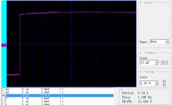
First is the classic step function. Not quite perfect but close enough. This is essentially the signal you get when you close a switch to a power supply.
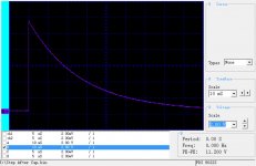
Next is the output across a 10,000 ohm resistor when the step function is passed through a capacitor with 5% "D" according to my bridge. Some folks seem to confuse this with linear algebra's definition of linearity, but clearly the graph is not a straight line.
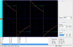
Third is a classic 20 hertz square wave image (Not perfect) and the square wave passed through the capacitor of 2.2 uF. Note that due to phase shift the apparent amplitude has increased by what looks like enough the perception may be the tone is louder. This is due to the phase shift that may also present itself in addition to the increase in amplitude.
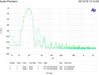
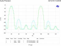
Fourth is an FFT of the 20 hertz sine wave passed through the higher DA capacitor compared to a better one built intp the AP unit. A quite dramatic increase in the harmonic distortion.
Finally is the IM distortion caused in both the good capacitor and the high DA one. Note there are always side bands due to the heterodyne caused by the nonlinear capacitor VI curve. Much worse with the high DA capacitor.
Naturally the curves are real as demonstrated by the 60 hertz incursions.
First is the classic step function. Not quite perfect but close enough. This is essentially the signal you get when you close a switch to a power supply.
Next is the output across a 10,000 ohm resistor when the step function is passed through a capacitor with 5% "D" according to my bridge. Some folks seem to confuse this with linear algebra's definition of linearity, but clearly the graph is not a straight line.
Third is a classic 20 hertz square wave image (Not perfect) and the square wave passed through the capacitor of 2.2 uF. Note that due to phase shift the apparent amplitude has increased by what looks like enough the perception may be the tone is louder. This is due to the phase shift that may also present itself in addition to the increase in amplitude.
Fourth is an FFT of the 20 hertz sine wave passed through the higher DA capacitor compared to a better one built intp the AP unit. A quite dramatic increase in the harmonic distortion.
Finally is the IM distortion caused in both the good capacitor and the high DA one. Note there are always side bands due to the heterodyne caused by the nonlinear capacitor VI curve. Much worse with the high DA capacitor.
Naturally the curves are real as demonstrated by the 60 hertz incursions.
Attachments
Last edited:
The thing about the relays for output protection is they are low demand. That is in a 10 year period if they are power cycled twice a day every day, you are only talking 7300 cycles.
The 6A relay I tested which was used in a 2A rated service is expected to operate beyond 200,000 cycles in it's life.
Inrush current peaked from 19-27A for 200W light bulbs used in the lamp load test. (we also do a NEMA starter test, but that is only a 6000 cycle test.
I looked up the data on one batch of 25 relays I tested, and it had a mean of 255,397 cycles, and a Std Dev of 143,402. The test was stopped at 500,000 cycles with 4 relays still operating, so the Std-Dev would have shrunk slightly and the mean increased given that the remaining relays might have run a while longer. With 84% failed, it is not likely to be significant.
The large Std-Dev shows the likelihood of early failures being significant for high volume products.
- Status
- Not open for further replies.
- Home
- Member Areas
- The Lounge
- John Curl's Blowtorch preamplifier part II