Oh.. Given Jan has presented what appears to be a plot from what is likely to be LTSpice, n008 with colours changed.... Please Please Please try breaking the loop as suggested in my previous examples, and the TI example, and plot the 'loop gain'. It is much more informative.
Yes. In as much as you might mess about on the bench I mess about in Spice before getting to the bench. Take a guess as to what might be causing the problem and change something around it and see what happens.
Ultimately you will have to sacrifice bandwidth.
Crossed messages.
Yes. In as much as you might mess about on the bench I mess about in Spice before getting to the bench. Take a guess as to what might be causing the problem and change something around it and see what happens.
Ultimately you will have to sacrifice bandwidth.
Crossed messages.
Jan,
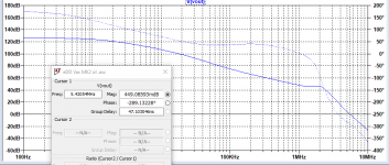
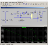
look at where the gain plot crosses over the 0dB.
The steepness of the gain plot is much more than 6dB/Octave.
For a non complex roll off the steepness must be <9dB/octave at the cross over.
Now look at the phase at 0dB. It is 290degrees. That has moved from +50degrees in the midband. A phase change of 340degrees. You should be looking for <<180degrees, preferably around 100 to 120degrees, giving a phase margin of 80 to 60degrees.
But there is something happening that I don't understand. The gain plot has a bump at 2MHz and it starts to roll off at 2kHz. Both of these look non standard.
The phase changes far more than most other loop gain plots show. Confusing for one that still cannot design amplifiers, I too don't grasp the intricacies of zeros and poles and how to manipulate them to our advantage.
Open loop...
Jan
Assuming you have measured the right thing then that looks quite horror show.
I guess you may have inserted an AC voltage source as suggested but rather than plotting V(a)/V(b) you have used a Voltage Controlled Voltage Source, E, to extract the answer.
Extreme Kudos.
You probably know but LTSpice lets you label nodes. Then it lets you edit the equation in the plot window. Right Click and...
The mention of VAS makes me think you are in valve territory.
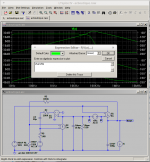
I've just scored this.. Do I change C1 or R3 to get it working and where are C1 and R3?
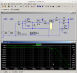
Best I get is that between 10KHz and 100KHz gain drops from 110dB to 70dB or 40dB/Decade, second order... two poles.
Then it tries to go from about 70dB to 50dB from 100KHz to 1MHz or 20dB/Decade, first order... one pole, before completely giving up and going on holiday above 1MHz.
Since you are being shy then without knowing what the actual circuit is the best I might suggest is that you pick the 60dB/300KHz point and find a location in the circuit where you can reduce the gain by 1,000.
Err... just to be more unhelpful using a resistor possibly in series with a capacitor. Previous example.
...
Attachments
Last edited:
I made it completely open loop. Plotted output with a nominal 1V input, no feedback (the amp is DC stable after some fiddling). So that does give me the open loop response, right?
But you put me on a track, I will check tomorrow, got to run now.
Edit: quick fiddle: there are two feedback opamp- stages in the forward path, connected through a linear optocoupler. I think the bump(s) at 2MHz are due to the opamps. See attached, opamps compensated.
Jan
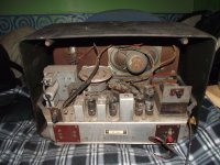
PS Nice radio. I usually place these in the dishwasher for a single chinaware cycle. Works like a charm. Though, may loosen labels...
But you put me on a track, I will check tomorrow, got to run now.
Edit: quick fiddle: there are two feedback opamp- stages in the forward path, connected through a linear optocoupler. I think the bump(s) at 2MHz are due to the opamps. See attached, opamps compensated.
Jan
PS Nice radio. I usually place these in the dishwasher for a single chinaware cycle. Works like a charm. Though, may loosen labels...
Attachments
Last edited:
I made it completely open loop. Plotted output with a nominal 1V input, no feedback (the amp is DC stable after some fiddling). So that does give me the open loop response, right?
But you put me on a track, I will check tomorrow, got to run now.
Edit: quick fiddle: there are two feedback opamp- stages in the forward path, connected through a linear optocoupler. I think the bump(s) at 2MHz are due to the opamps. See attached, opamps compensated.
Jan
PS Nice radio. I usually place these in the dishwasher for a single chinaware cycle. Works like a charm. Though, may loosen labels...
Probably not.
Unless you cough the full circuit including your measurement method I will have no idea what you are talking about but no doubt you will tailor the PCB parasitics to arrive at something that appears to work.
Of course I may be failing to explain things coherently myself.
In respect of sticking the radio in the dishwasher do I have to use the new eat the detergent first meme and then slap it in the tumble dryer afterwards or should I just go in and arbitrarily smash things about with a lump hammer?
No I am serious. I have done this with power amps, vintage Tek scopes and Lambda power supplies. The power amp power switch needed deox afterwards, other than that, no sweat. Equipment was squeaky clean, like new, even inside!
Think about it, crystal glasses come out brilliant with no residue at all!
Jan
Think about it, crystal glasses come out brilliant with no residue at all!
Jan
No I am serious. I have done this with power amps, vintage Tek scopes and Lambda power supplies. The power amp power switch needed deox afterwards, other than that, no sweat. Equipment was squeaky clean, like new, even inside!
Think about it, crystal glasses come out brilliant with no residue at all!
Jan
Uhm-Kay. Just before I follow through on your advice do I use WD-40 or GT85 for final finishing?
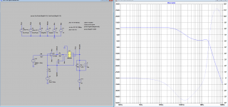
It looks to me like Jan is making a big feedback loop around an oscillator. It is sometimes possible to get something like that stable, but it usually isn't easy. Is there a way you can better compensate the local loops?
Comparing the magnitude and phase plots in his graphs, it looks like this is the pole-zero pattern:
Post 125, open loop gain:
Two left-half-plane poles around -4000 pi rad/s
Left-half-plane zero around -400 pi krad/s
Two complex pole pairs, one in the left half plane and one in the right half plane, about 4 pi Mrad/s from the origin
Post 122, also open loop: this is the best behaved one, the complex pole pairs are now in the left half plane. Circuit-wise, what's the difference with post 125?
Post 117, closed loop: negative real pole and two complex pole pairs, one in the right half plane
I don't think it is necessary to do any after-treatment. This unit will look like new!
Jan
OK... Before/After. I am beginning to lose faith here.
Now what?
Attachments

Edit: quick fiddle: there are two feedback opamp- stages in the forward path, connected through a linear optocoupler. I think the bump(s) at 2MHz are due to the opamps. See attached, opamps compensated.
There appear to be complex right-half-plane poles in the open loop gain about 4 pi Mrad/s from the origin (post 125). Could it be that one of these op-amp stages is oscillating all by itself?
Picture 1) The 2KHz pole is not atypical. Whist Jans circuit may not be represented by the following it is to be expected with a resistive load paralleled with an output capacitor.
Picture 2) Jan mentions two opamps and an opto-coupler. It is possible to arrive at a situation where the opamps run out of steam at 1MHz and... the opto-coupler does the same.
Then you might end up with the circuit going third order, 60dB/Dec with an additional 270° phase lag at around 1MHz to add to that already present at lower frequencies..
Again without knowing or seeing the actual circuit we will just be guessing as to what might really be going on. I do not think there is a right half plane zero in the circuit.
It would be unusual but if present would show up as a section with rising gain but decreasing phase. I might have that upside down.
Attachments
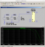
I think you are right. The opto is a linear HCNR200 surrounded by opamps.
I have little time at the moment (just delivered my g/f to the hospital) but will investigate. Thanks.
Edit: on the dishwasher procedure, be sure to leave it closed until all moisture has been heated off. Also place such that there are no cavities were water can collect, but make sure it all can run off....
Jan
Attachments
Last edited:
This is an oscillator. There is a bump and after the bump the magnitude goes down faster, but the phase goes up steeply, indicating a rather complex pole pair in the right half plane.
You could connect C1 to the other side of R1 and play with its value, then the pole formed by R1 and the capacitance of the LED is out of the local loop at high frequencies. If that doesn't help enough, also replace the LT1028 with an LT1128.
You could connect C1 to the other side of R1 and play with its value, then the pole formed by R1 and the capacitance of the LED is out of the local loop at high frequencies. If that doesn't help enough, also replace the LT1028 with an LT1128.
Last edited:
It might not be what you originally envisaged but...
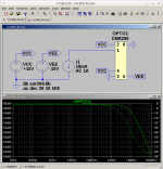
HCNR200
HCNR200 HCNR201 High Linearity Analog Optocouplers (389 KB)
https://www.mikrocontroller.net/attachment/108367/AvagoHCNR200_MOD.txt
http://www.linear.com/docs/3480
You really do like these high Gain-Bandwidth devices and as Marcel suggests they may not be doing you any favours.
Other than stopping things from going fuzz at the output the output photodiode/amplifier does not really enter into stability considerations.
You are more concerned with the primary side LED drive/Photodiode feedback.
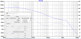
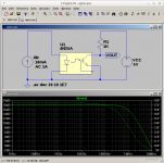
Figure 1) Loop Response. Again this is breaking the Loop with VAC and measuring across it. Crossover is about 800KHz First order with 90 degrees of phase margin. No... I cannot explain what is happening to Gain and Phase above 1MHz.
Figure 2) Output Response. Setting VAC to 0V and V1 to 1V. 3dB down at 500KHz and then all sorts of shed happens. Unless you are going to include that in a feedback loop then you do not really care.
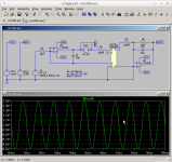
Figure 3) 1KHz Transient Response. Apparently, at least in Spice, the thing does what it says on the tin. 1V in with 500mV Pk-Pk gives 1V out and 500mV Pk-Pk.
HTH
HCNR200
HCNR200 HCNR201 High Linearity Analog Optocouplers (389 KB)
https://www.mikrocontroller.net/attachment/108367/AvagoHCNR200_MOD.txt
http://www.linear.com/docs/3480
You really do like these high Gain-Bandwidth devices and as Marcel suggests they may not be doing you any favours.
Other than stopping things from going fuzz at the output the output photodiode/amplifier does not really enter into stability considerations.
You are more concerned with the primary side LED drive/Photodiode feedback.
Figure 1) Loop Response. Again this is breaking the Loop with VAC and measuring across it. Crossover is about 800KHz First order with 90 degrees of phase margin. No... I cannot explain what is happening to Gain and Phase above 1MHz.
Figure 2) Output Response. Setting VAC to 0V and V1 to 1V. 3dB down at 500KHz and then all sorts of shed happens. Unless you are going to include that in a feedback loop then you do not really care.
Figure 3) 1KHz Transient Response. Apparently, at least in Spice, the thing does what it says on the tin. 1V in with 500mV Pk-Pk gives 1V out and 500mV Pk-Pk.
HTH
Attachments
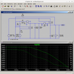
This is a lot better than Jan's graph, so apparently connecting the compensation capacitor to the other side of the 100 ohm and tweaking its value does the trick. Still, the input-to-output response has a nasty bump. Is that due to the second op-amp? The LT1028 is not unity-gain stable and has a high gain-bandwidth product, so the value of C2 could be rather critical.
By the way, if I understand Jan's posts correctly, he is going to include this circuit into an overall feedback loop. Even if he weren't, I would definitely care about the bump in the second response.
By the way, if I understand Jan's posts correctly, he is going to include this circuit into an overall feedback loop. Even if he weren't, I would definitely care about the bump in the second response.
It might not be what you originally envisaged but...
HCNR200
HCNR200 HCNR201 High Linearity Analog Optocouplers (389 KB)
https://www.mikrocontroller.net/attachment/108367/AvagoHCNR200_MOD.txt
http://www.linear.com/docs/3480
You really do like these high Gain-Bandwidth devices and as Marcel suggests they may not be doing you any favours.
Other than stopping things from going fuzz at the output the output photodiode/amplifier does not really enter into stability considerations.
You are more concerned with the primary side LED drive/Photodiode feedback.
Figure 1) Loop Response. Again this is breaking the Loop with VAC and measuring across it. Crossover is about 800KHz First order with 90 degrees of phase margin. No... I cannot explain what is happening to Gain and Phase above 1MHz.
Figure 2) Output Response. Setting VAC to 0V and V1 to 1V. 3dB down at 500KHz and then all sorts of shed happens. Unless you are going to include that in a feedback loop then you do not really care.
Figure 3) 1KHz Transient Response. Apparently, at least in Spice, the thing does what it says on the tin. 1V in with 500mV Pk-Pk gives 1V out and 500mV Pk-Pk.
HTH
MF, you are using the photodiodes in photo-voltaic mode, correct? My use is in photo-conductive mode which should give wider bandwidth. That may change things.
Although, looking at your graphs, maybe photo-voltaic mode is easier to tame, and the BW isn't too bad.
Jan
Edit: you may be interested in this: https://www.vishay.com/docs/83708/appn50.pdf (The IL300 is 2nd source for the CNR200 and vice versa).
Jan
Jan
In wet finger waving territory the nasty bump, input to output, is possibly an accumulation of poles due to diode capacitances and there might not be much that can be done about it...
I did notice that Jan was applying reverse bias to the photodiodes. AFAIK the idea is that junction capacitance falls as the reverse bias is increased. Unfortunately if I set up a test then the Spice Model does not appear to exhibit this behaviour.
Figure 1) Zero Bias.
Figure 2) Reverse Bias.
As others have mentioned sometimes Spice does not do it all and you can add that I am not clever enough to look inside the actual circuit and figure out why that particular behaviour is apparently missing.
Looking at those curves everything appears quite benign. Photodiodes and for that matter LEDs are supposed to be intrinsically fast devices, crippled by junction capacitances.
Also something else in the circuit might be getting hammered. In particular the opamp is being asked to supply close to its maximum rated current.
I'll try fiddling with something else but at this point we may be on the edge of model limitations or, more likely my experience.
Attachments
- Status
- This old topic is closed. If you want to reopen this topic, contact a moderator using the "Report Post" button.
- Home
- Amplifiers
- Power Supplies
- Op amp Linear power supply