Двухполярный малошумящий источник питания с высоким подавлением входной помехи
.
The bipolar low-noise power supply with high suppression of an input noise, HIGH (LOW) PSRR.
This is a article and forum about circuit, which I posted.
But in Russian.
Translate forum with GOOGLE.COM translater.
.
.
The bipolar low-noise power supply with high suppression of an input noise, HIGH (LOW) PSRR.
This is a article and forum about circuit, which I posted.
But in Russian.
Translate forum with GOOGLE.COM translater.
.
Last edited:
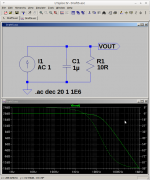
Is C1 an ideal capacitor or a model of a typical electrolytic capacitor?
Good question
") If you look at the image above your post you will see the symbol of the cap is different... its a 'real' one with 1 ohm E.S.R.
If you look at the image above your post you will see the symbol of the cap is different... its a 'real' one with 1 ohm E.S.R.I looked into this and tried several different types including ideal PLUS a series resistor. All seemed to work well.
Attachments
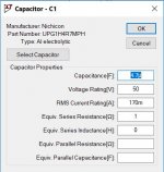
I had noticed the different symbol, I just wasn't sure what it stands for. I don't use LTSpice very often.
If I understand it correctly, you use the ESR for frequency compensation, so C1 is not allowed to be replaced with a film capacitor or a low-ESR electrolytic unless you add an extra resistor. Is that correct?
If I understand it correctly, you use the ESR for frequency compensation, so C1 is not allowed to be replaced with a film capacitor or a low-ESR electrolytic unless you add an extra resistor. Is that correct?
That's pretty much it, yes.
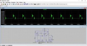
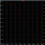
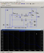
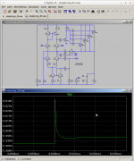
This shows an ideal cap vs ideal plus 0.1 ohm. The spiky nature of the output voltage is simply the very noisy raw supply reflecting into the result, however the voltage scale puts the absolute amplitude into perspective. The ideal cap is tending toward high frequency instability. An ESR of as high as 5 ohms was still OK.
This shows an ideal cap vs ideal plus 0.1 ohm. The spiky nature of the output voltage is simply the very noisy raw supply reflecting into the result, however the voltage scale puts the absolute amplitude into perspective. The ideal cap is tending toward high frequency instability. An ESR of as high as 5 ohms was still OK.
Attachments
Under stationary sine wave excitation you can substitute jω for s, but you don't substitute j for s. That is, XC = 1/sC, not XC = 1/sωC.
Thank you for the correction.
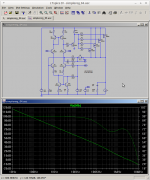
2 poles at 'DC'. One due to the op-amp one due to the D45H11 driving the output capacitor. ESR zero just above 10KHz.
I'm not seeing any poles at 'DC' ; Instead I see the first pole at 1.1 Hz, which coincidentally is very close to the opamp's pole frequency: datasheet figure attached.
_
Attachments
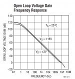
I'm not seeing any poles at 'DC' ; Instead I see the first pole at 1.1 Hz, which coincidentally is very close to the opamp's pole frequency: datasheet figure attached.
_
Fine.
Let's define DC as being Don't Care frequencies. Obviously you do care about their effects at higher frequencies, in particular at crossover, but...
Picture 1) Don't Care.
Picture 2) Don't Care.
Picture 3) Don't Care.
The poles are at different frequencies but crossover occurs at the same frequency and the phase lag is at or is approaching 90°.
Attachments
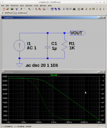
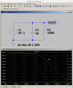
I'm not seeing any poles at 'DC' ; Instead I see the first pole at 1.1 Hz, which coincidentally is very close to the opamp's pole frequency: datasheet figure attached.
_
Oh... Yes you are seeing the op-amps pole frequency. The other pole is due to the Darlington driving the output capacitor. The wrong term would be its output admittance which, in effect, appears in parallel with the output capacitor via the input supply.
...
Attachments
Last edited:
I'm not seeing any poles at 'DC' ; Instead I see the first pole at 1.1 Hz, which coincidentally is very close to the opamp's pole frequency: datasheet figure attached.
_
Depending on one's point of view, either you are taking MorbidFractal too literally or MorbidFractal is expressing him- or herself too inaccurately.
From the context I understand that by a "pole at DC" MorbidFractal means a factor s + alpha in the denominator of the transfer function of the loop gain, with the modulus of alpha much smaller than the natural frequency omega_n of the closed loop.
So whether the pole is exactly at 0 rad/s or at -2.2 pi rad/s or at -200 rad/s doesn't matter much. As long as the loopgain-poles product stays the same and as long as the modulus of the pole is much smaller than the natural frequency omega_n of the closed loop, the closed-loop bandwidth and quality factor say nearly the same. (It may matter for the DC accuracy, but that's a different subject.)
How weird to assign your own private and idiosyncratic meaning to the term 'DC', which everyone else with a BSEE understands to mean 'zero frequency'.
But post #87 asserts that a pole at 159 Hz is a DC pole. A pole at 1590 Hz is also a DC pole. A pole at 15.9 kHz is also a DC pole. How weird.
You have trained me and perhaps other readers, to be skeptical of future bold assertions and confident claims -- they might be the result of re-defining standard terms in nonstandard ways. It has happened before.
How weird to assign your own private and idiosyncratic meaning to the term 'DC', which everyone else with a BSEE understands to mean 'zero frequency'.
But post #87 asserts that a pole at 159 Hz is a DC pole. A pole at 1590 Hz is also a DC pole. A pole at 15.9 kHz is also a DC pole. How weird.
You have trained me and perhaps other readers, to be skeptical of future bold assertions and confident claims -- they might be the result of re-defining standard terms in nonstandard ways. It has happened before.
I think MarcelvdG gets it. You, on the other hand, wish to be 'puritanical' and 'play the man'. In the present context Don't Care is a perfectly reasonable interpretation for the purposes of arriving at a solution.
It might be the case that having a, still wet behind the ears, BSEE is in fact a barrier to arriving at solutions. If I have to wave my willy then I have only got a BSc Honours Applied Science (Phys/Chem), it was only a 2)ii), and a bit of experience.
Looking back through the thread it would seem that I have been the only one who has presented, nominally, stable circuits. Of course if you wish to state I am 'completely' wrong then that is fine by me. Just try not to play troll and insist that others comply with your point of view.
Alternative fact of the week: Burning politicians in the Netherlands - Baltimore Sun
Otherwise... I get to do this...
...
Attachments
Last edited:
You are making all sorts of unproven assumptions about Mark's motivations now. It could be that he simply didn't understand you because he took your remarks about poles at DC literally. Things like that happen to me quite regularly; having Asperger's, I tend to take what people say literally at first, and then try to decipher what they may mean - and I'm not always successful at that second step.
I think most linear regulators are inherently unstable, its the nature of the beast, but what surprised me here was just how 'resistant' this one was to various measures thrown at it. That's why it needed a re-think.
So...
In post #1 mention was made of having a P channel power FET available. So lets use it. This allows two advantage to my way of thinking. The 'level shifting' zener can be dropped thanks to the higher Vgs needed to get the device to conduct (compared to traditional Vbe for the transistor) and most importantly, it relaxes the current demands on the opamp output which would be unable to support more than around 15ma. That's important for high load currents if we used a single series pass transistor.
To tame the stability we now have a small electrolytic on the regulator output. The feedback network also has a small cap added that seems to help under certain conditions.
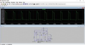
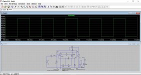
This shows the output voltage (set to 12.6 volts) and a new 'noisy' raw supply which has both significant impedance and also simulated ripple superimposed on it.
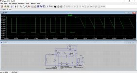
The second graph shows the ripple at a transition where the load current is abrubtly applied.
Mooly,
Yes I have an IRF9540 p channel mosfet. I am gone this week and will not be able to test the circuit. I do not have 4.7uf Electrolytic I only have 22uf electrolytic. I am confused by all the math and talk of poles from morbid fractal, but I am trying to read some other books about these topics. I am do not have anyway to inject an 1 volt ac signal into this set up. I do not have the equipment to do this.
22 uF will probably also work if the ESR is high enough - so if it is a cheap run-of-the-mill electrolytic and no fancy low-ESR device.
Can you inject a low-frequency square wave somewhere? Oscilloscopes often have a built-in square wave oscillator for probe calibration. The response to a small square wave injected at the reference or added to the load current also shows you whether the stability is good, marginal or non-existent.
Can you inject a low-frequency square wave somewhere? Oscilloscopes often have a built-in square wave oscillator for probe calibration. The response to a small square wave injected at the reference or added to the load current also shows you whether the stability is good, marginal or non-existent.
A 22uF electrolytic seems fine in simulation. A 22uF ultra low ESR or similar showed a tendency to instability.
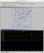
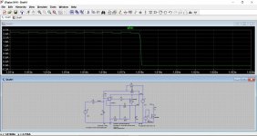
This is using Marcels idea of modulating the reference with a squarewave. Shown is the zener voltage and the output voltage at the transition between full load current and no load current. Last shot is the load current. This is with a 22uF cap.
This is using Marcels idea of modulating the reference with a squarewave. Shown is the zener voltage and the output voltage at the transition between full load current and no load current. Last shot is the load current. This is with a 22uF cap.
Attachments
It's a shame to see MorbidFractals excellent practical demonstrations of reliable oscillation-free power & control loops ignored like this, in favour of arbitrary methods of stability testing.
Closing the loop around an op-amp-driving-a-power-transistor without checking the phase margin is like flying blind.
A circuit may appear to be stable at first measurement, but all kinds of things that affect the open-loop gain (temperature, sample-to-sample variation of transistors, load current, reactive loads etc etc) are likely to change in real life, and between one person's build and another.
Unchecked, uncompensated designs are highly likely to go bad a some point.
But if your circuit has, say 40-90° of phase margin, you can build with more confidence - and preferably do some practical testing.
Using the LTSPICE circuits that MorbidFractal has offered generously, you can explore all this. Look at the phase shift between A and B on his .asc files, especially as the gain approaches 1 at higher frequency (the « crossover » 0dB).
If anyone has not studied control systems, and does not know what "phase margin " is: try to read the "frequency compensation" paragraphs in Horowitz & Hill.
On the other hand, anyone not wishing to learn and measure, but just build a prepared design would be better served by using one of the circuits he presented that show good phase margin - including the one with the opamp (post 76), if desired.
Last edited:
I don't think it is that simple Rod. We all know that especially in the area of stability, simulations are notoriously unreliable because all the practical parasitics are not included in the circuit.
What you call 'arbitrary methods' could easily be done as an reliable test of the actual hardware build, no uncertainties then. An open loop bode plot is a project in itself.
And some people are comfortable with one perspective, others with another. No immediate reaction does not mean something is ignored.
Jan
Simulations are there simply to make it easy, before you begin soldering. And « practical parastitics » are perfectly easily accommodated in simulations, and can be varied with ease.
I am not suggesting you do not apply practical testing! Of course, measuring the phase margin of your prototype, by breaking the loop in exactly the way shown in the plots, is the proper way to confirm the results.
I am not suggesting you do not apply practical testing! Of course, measuring the phase margin of your prototype, by breaking the loop in exactly the way shown in the plots, is the proper way to confirm the results.
- Status
- This old topic is closed. If you want to reopen this topic, contact a moderator using the "Report Post" button.
- Home
- Amplifiers
- Power Supplies
- Op amp Linear power supply