An externally hosted image should be here but it was not working when we last tested it.
An externally hosted image should be here but it was not working when we last tested it.
An externally hosted image should be here but it was not working when we last tested it.
Groupdelay, phase and THD. Red curve is the new improved mounting and with 2 hours of 15 Hz at xmax to soften the suspensions..
An externally hosted image should be here but it was not working when we last tested it.
That big dip @200 Hz appears quite a bit higher than suggested in the model. That suggests that either the parameters of the sim (path length's, CSA, etc.) are not the best match for what was built, or what was built was so large that the folds are affecting the accuracy of Hornresp predictions down to ~160 Hz, where it looks like the first null is sim'd to occur. Which post has the dimensions of the ROAR12? If I have a chance this week, I could try to build a sim for it, to see if it matches the sim that you came up with.
As I mentioned before, an impedance curve can quickly tell us if the build was a good match for the sim. Are you able to perform one? I see that you're using REW for the FR curves. With a simple jig, it can also be used to measure impedance.
An externally hosted image should be here but it was not working when we last tested it..
GD down at 40 Hz looks a little high, but the response is pretty far down at this point anyway. The GD between 60 Hz and 120 Hz looks a bit scary though!. How audible is it? What sort of LP filtering do you use when integrating the ROAR12 with other speakers to cover the rest of the spectrum?
A trick I often use to check how close my sims are to the measured cabinet is to export the response as text from HR and then import it into REW to compare with the measurements. If the 2 are way off then the sim is not representative of the system.
Even taking the time to closely match the sim to the measured system characteristics will never produce a perfect match. However you can get close.
Even taking the time to closely match the sim to the measured system characteristics will never produce a perfect match.
However you can get close.An externally hosted image should be here but it was not working when we last tested it.
Thanks Josh Ricci!! It is a great tip.
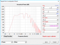
The red line is the Hornresp sim exported to REW and the green line is the mesurement made with REW.
An externally hosted image should be here but it was not working when we last tested it.
Here is the Hornresp data I use for my ROAR12 with my B&C 12PS100.
Cheers,
Johannes
The GD between 60 Hz and 120 Hz looks a bit scary though!. How audible is it? What sort of LP filtering do you use when integrating the ROAR12 with other speakers to cover the rest of the spectrum?
It does not sound resonant or bad in any way crossed over 48 dB/octave @ 120 Hz.
With a 150 Hz 24 dB/octave LP you start to hear the frontresonator. It is usable, but I prefer a lower and steeper LP filter.
I have built a measuring rig to make impedance measurments, but I need a better soundcard for my laptop. There is to much interference with the built in microphone input and the headphone output. I can't get it to work at all. It just hangs on "calculating TTF" for hours and then freezes completely.
I am working on it. I hope I can post impedance graphs soon.
Regards,
Johannes
An externally hosted image should be here but it was not working when we last tested it.
An externally hosted image should be here but it was not working when we last tested it.
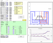
Here is imported Hornresp phase and GD (red curves) and measured phase and GD (green curves).
My neighbor does not like when we measure my ROAR outdoors, so this measurements are made indoors. I guess some of the midbass ripple is due to room acoustics.
I will try to take new measurements outdoors soon. This is the best I can manage right now.
Regards,
Johannes
An externally hosted image should be here but it was not working when we last tested it.
An externally hosted image should be here but it was not working when we last tested it.
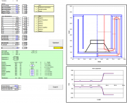
Here is imported Hornresp phase and GD (red curves) and measured phase and GD (green curves).
My neighbor does not like when we measure my ROAR outdoors, so this measurements are made indoors. I guess some of the midbass ripple is due to room acoustics.
I will try to take new measurements outdoors soon. This is the best I can manage right now.
Regards,
Johannes
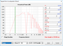
The response measurement and GD curve between 75 and 110Hz is odd and doesn't seem to match the sim at all. This was measured inside? What was the distance of the microphone?
If you get another chance try to take another set of measurements with the mic within a few cm of the exit plane of the radiating duct/s. Also move the cab to the center of a large room if possible. This should reduce any effects from the room acoustics as much as possible and help determine whether the roughness through the XO region is inherent to the cab or due to outside influences during the measurement.
Today was a good day, we visited a local sound rental company and gave the ROAR12 a bit of a test, I must say it really impressed me, and judging from statements and questions from the guys at the sound company it impressed them as well ")
It sounded really nice at some decent levels, nice punch, good definition, and a good low end response given the tuning and loading.
We took some pictures and performed measurements, the place was about 150m2 and we placed it so that the closest distance to any wall was ~4m, measurements where taken at 1m and 5m, in the case or the 5m the room influences where evident.
All in all I'm got a good impression of the ROAR12 and believe it could perform even better if loaded with a more powerful driver.
I'm got a good impression of the ROAR12
If you have any chance to pick impression about ROAR18 in any closed hall/apartment - use it.
You granted with a sea of new enchantments.
YouTube
Having some fun with a ROAR12, a Powersoft K10 and some nice sounding Prophone top loudspeakers based on B&C 15 inch coaxial drivers.
The ROAR12 impressed us all. Clean, punchy and very tactile physical bass from a reasonably small and easily built box.
YouTube
Without the top system it is easy to hear the whole room resonating from the bass from a single 12 inch driver.
It is easy to integrate with the top system.
Even at peaks above 1 kw we could not push the driver to more then +-5 mm cone excursion. It is quite strange. The ROAR seems to hold the cone very firmly all the way down to 32 Hz or so.
It just occurred to me that the layout of the ROAR is very close to the layout of the Cyclops. The only thing significantly different is that the Cyclops has an extra fold at the back, which results in shorter box for the same path length. The simulated response curves are pretty close too (see attached). As I've got a spreadsheet that can (theoretically) optimize a Cyclops fold, it shouldn't take much to change it to use a ROAR fold as well. If I have some time this weekend, I'll have a look at it.
Attachments
It just occurred to me that the layout of the ROAR is very close to the layout of the Cyclops. The only thing significantly different is that the Cyclops has an extra fold at the back
Superficially there are similarities between the Cyclops and the ROAR.
The Cyclops has a multi-stepped expansion, but is in many ways more of a "normal" tapped horn then a ROAR.
When you keep the expansion you loose what makes the ROAR unique.
One could claim that the ROAR is a two step expansion tapped horn, but this is an oversimplification that makes you miss the whole point of the design.
The ROAR is all about maximizing the nonlinear behavior to an advantage instead of the normal disadvantage found in bass reflex ports and similar designs.
Yesterday we tested the ROAR12 at high power levels and we all made the observation that cone excursion is much less then predicted. A single B&C 12P100 could keep up in most ways with two B&C 18TBX100 each powered by a pro audio 1050 watt class D module. The ROAR12 could energize the room in a very different way. We could hear the roof, walls and interior rattle and buzz at much lower spl then with two 18TBX100 in BR boxes even though they were tuned much lower and had more low end "grunt".
We did not use any HP filtering or limiting and we pushed the ROAR12 hard with very bass heavy electronic music. Despite this we could not push the driver to more then 5 mm one way cone excursion (10 mm peak to peak) with the Powersoft K10.
The ROAR series seams to thermally limit way before the 12PS100 runs out of xmax, despite the lack of HP filtering. Quite strange behavior from a 45 Hz tuned "tapped horn".
Cheers,
Johannes
As far as the general layout is concerned there are similarities in how the internal structure is orientated, and if modified so that you alter the lengths of the segments used, take others away, and remove the expansions in the steps then it becomes a ROAR, but at that stage it is quite different from the cyclops design, but maybe the spreadsheet can be used if altered accordingly, it's a good idea and it would be interesting to see if it works out, thank you.It just occurred to me that the layout of the ROAR is very close to the layout of the Cyclops. The only thing significantly different is that the Cyclops has an extra fold at the back, which results in shorter box for the same path length.
I have seen comparisons being made between Cyclops and ROAR before, some even claiming it is no different, this to me is not true, the two main differences are that ROAR uses one constant area segment pre tapping and another post tapping where the latter acts as a QW resonator after the summation, the QW resonator needs a certain length to work as intended, therefore the depth of the box cannot be shortened without losing this function.
Seeing as the QW resonator length is required for the desired function, the driver needs to be as far in as possible to make the box as shallow as possible, the way to accomplish this is by using the depth granted by the QW resonator and fold the path(s) next to it, even more so if you go split path.
This way you maximize the resonator length in a given total box depth, but you could do it either way, but the total box depth will grow if you introduce multiple folds on the rear side of the driver baffle.
Last edited:
It just occurred to me that the layout of the ROAR is very close to the layout of the Cyclops. The only thing significantly different is that the Cyclops has an extra fold at the back, which results in shorter box for the same path length. The simulated response curves are pretty close too (see attached). As I've got a spreadsheet that can (theoretically) optimize a Cyclops fold, it shouldn't take much to change it to use a ROAR fold as well. If I have some time this weekend, I'll have a look at it.
Turns out that the mods were actually quite easy, but there is a catch. In putting together the spreadsheet, it's clear that Hornresp can't exactly sim the ROAR. That's because Hornresp will put the driver only at S3 or S4 in a TH sim, and the driver resides somewhere between those two points (but closer to S4) on the path. So the sim will be close, but it will always be a little off as well. I think this cane be improved by converting the front resonator to an expanding section, at which point the driver can be placed directly at S4, but then it would no longer be a ROAR.
Anyway, I've attached a copy of the workbook, if anyone wants to have a play with it.
Attachments
The ROAR is all about maximizing the nonlinear behavior to an advantage instead of the normal disadvantage found in bass reflex ports and similar designs.
I have no idea what you mean by that. I can't think of any reason that I'd want to "maximize the non-linear behavior" of any design. Quite the opposite in fact.
In any case I'm not really concerned about the labels. My focus is on the topology, and the closest match to the ROAR's topology is a TH with two non-expanding segments and an abrupt expansion between S3 and S4. As Hornresp is usually pretty good at modelling such alignments, I don't see why it should fail to do so, or at least come pretty close, in this case.
Thank you Brian! that way of setting up the hornresp paths was actually something we investigated in the beginning, what made us deviate from it was the front resonator the length, which needs to be set from the driver baffle to the aperture, so we realized the sim would not be 100% but perhaps more true due to the big influences of the QW resonator on the system.
Here is the response at 1m (with smoothing) of a ROAR12, no EQ or filtering applied, measured in a ~150m2 room, at a local sound contractors warehouse, 4m away from the closest wall, even so room acoustics are evident, sensitivity is not calibrated/true :

Given the autumn and winters here in Sweden outside measurements are hard to arrange, and we are located at the coast (windy) otherwise an outside true 2PI measurement would have been made.
Here is the response at 1m (with smoothing) of a ROAR12, no EQ or filtering applied, measured in a ~150m2 room, at a local sound contractors warehouse, 4m away from the closest wall, even so room acoustics are evident, sensitivity is not calibrated/true :
Given the autumn and winters here in Sweden outside measurements are hard to arrange, and we are located at the coast (windy) otherwise an outside true 2PI measurement would have been made.
Last edited:
I have no idea what you mean by that. I can't think of any reason that I'd want to "maximize the non-linear behavior" of any design. Quite the opposite in fact.
I can't understand why you would want to sacrifice up to 40 dB extra output from a bass"horn"?
If you want to avoid the nonlinear behavior of air in ducts you have to stay way below 120 dB sound pressure inside the duct at all times.
Quite boring I would say..
I think it is better to take advantage of the "problem" of nonlinear acoustics and dynamics.
A Lockheed SR71 operates in a whole series of nonlinear flows and dynamics, and I consider this a more fun and a more technical advanced airplane then a Piper J3 Cub that operates much closer to linear conditions.
There are some small superficial differences between the ROAR series and a Lockheed SR71, but you have to consider that we don't have the CIA breathing down our necks and throwing money at us, demanding stellar and spectacular performance regardless of budget during the development phase...
regards,
Johannes
http://www.acoustics.ed.ac.uk/wp-content/uploads/Theses/Skulina_David__PhDThesis_UniversityOfEdinburgh_2005.pdf
A great scientific study/article about the effects of nonlinear dynamics and acoustics in straight ducts.
I know there is some who think physics and scientific studies are triggering and they shun this knowledge and calling these principles "ridiculous" and a lot of other condescending expressions, but I can't ignore this just to protect their delicate feelings.
If one wants to use the nonlinear acoustics in a beneficial way like I strongly suspect Tom Danley does in his BC series, then the linked article above is a great start.
A great scientific study/article about the effects of nonlinear dynamics and acoustics in straight ducts.
An externally hosted image should be here but it was not working when we last tested it.
An externally hosted image should be here but it was not working when we last tested it.
I know there is some who think physics and scientific studies are triggering and they shun this knowledge and calling these principles "ridiculous" and a lot of other condescending expressions, but I can't ignore this just to protect their delicate feelings.
If one wants to use the nonlinear acoustics in a beneficial way like I strongly suspect Tom Danley does in his BC series, then the linked article above is a great start.
- Home
- Loudspeakers
- Subwoofers
- ROAR18