![images[1].png](/community/data/attachments/590/590398-3be3c1e4941cdbf17606da1877fc334a.jpg)
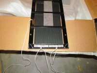
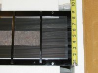
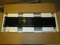
Hey guys! Need your help. I am trying to replace the old capacitors in my MK121-2A interfaces.
I have (3) total stacked together (see pics). The values I can read are 250V 10uf, 200V .47uf and 27 000 160v that's the little electrolytic cap on the end of the (2) yellow caps.
The schematic I have doesn't show the electrolytic and the .47uf is listed as a .01uf.
What should these values be? And should the electrolytic cap be left off or what should replace it.
I've already changed out the binding posts and old Monster wire and put on longer, bigger gauge AC Power cable.
Thanks for your help!
The caps shown in your photos are not factory stock, so don't try to relate what you see to the schematic. I highly recommend that you perform the C-Mod on your interfaces. This mod reduces high frequency distortion, and, reduces the value of the larger capacitor from 220-uF to 47-uF. This makes it much more practical to replace the electrolytic with a polypropylene. The modification is easy to do and involves readily obtainable parts.
The instructions for the C-Mod have been posted earlier in this thread (perhaps several times), but if you can't find it, I can post it again. I would do that now, but I'm currently not where I have access to my files.
The schematic diagram just posted by TYU is part of the C-Mod instructions, but without the rest of the instructions, it may lead you astray.
Recent postings of Cmod instruction here:...The instructions for the C-Mod have been posted earlier in this thread...
Acoustat Answer Man is here: post#1851
Acoustat Answer Man is here: post#1353
I recently stumbled on some pics of the panels on ebay...it does look like they continued the Spectra style segmentation....I've only seen photos of the Chinese panels. They do appear to be based on Acoustat's sheathed-wire design, and I'm assuming they continued with Spectra's segmented stators.
Attachments
The caps shown in your photos are not factory stock, so don't try to relate what you see to the schematic. I highly recommend that you perform the C-Mod on your interfaces. This mod reduces high frequency distortion, and, reduces the value of the larger capacitor from 220-uF to 47-uF. This makes it much more practical to replace the electrolytic with a polypropylene. The modification is easy to do and involves readily obtainable parts.
The instructions for the C-Mod have been posted earlier in this thread (perhaps several times), but if you can't find it, I can post it again. I would do that now, but I'm currently not where I have access to my files.
The schematic diagram just posted by TYU is part of the C-Mod instructions, but without the rest of the instructions, it may lead you astray.
Thank you so much! That was the info I was looking for. I will take your advice and do the "C" mod. It calls for a 10ohm, 25 watt resistor. Where does that get soldered? That was the only question I had after looking over the pdf of the "C" mod.
Thanks again!!!
Thank you so much! That was the info I was looking for. I will take your advice and do the "C" mod. It calls for a 10ohm, 25 watt resistor. Where does that get soldered? That was the only question I had after looking over the pdf of the "C" mod.
Thanks again!!!
I've attached a expanded set of directions that should guide you on mounting the resistor. The two added drawings were not included in the previous C-Mod instructions because I was not in possession of them at the time. I hand-drew these in 1986 (back in the pencil and vellum days) but didn't have copies. Then I found them on the web. Funny how things come around like that.
Attachments
FWIW, the drawings were part of your details MK121A-to-C conversion kit instructions(pg 7, 11) posted here:... The two added drawings were not included in the previous C-Mod instructions because I was not in possession of them at the time.
Acoustat Answer Man is here: post#1851
Thanks again! I do not have the medallion transformers. I am assuming that doesn't matter on the part(s) we are talking about?
The C-Mod is independent of the Medallion Transformers. The C-Mod can be performed on any of the MK-121, 131 or 141 interfaces, whether or not they have Medallion transformers. It does not apply to the Spectra series.
The C-Mod is independent of the Medallion Transformers. The C-Mod can be performed on any of the MK-121, 131 or 141 interfaces, whether or not they have Medallion transformers. It does not apply to the Spectra series.
Thank you again so much! I ordered a few of the parts already. What is your feeling towards "Boutique" parts?
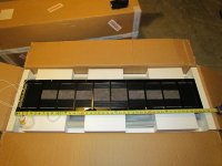
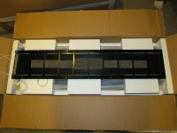
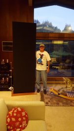
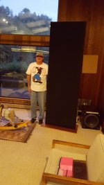
Scale of the Spectra 66's
Hi Andy, I submitted these 2 pictures in reference to one of your recents post mentioning the scale of the Spectra 66's. I had these pictures taken when I bought my pair of Spectra 66's from the seller in Sequel, Ca. At 5" 10" I look puny in size compared to the 7"10" height x 29" wide size of the Spectra 66's.
Hi Andy, I submitted these 2 pictures in reference to one of your recents post mentioning the scale of the Spectra 66's. I had these pictures taken when I bought my pair of Spectra 66's from the seller in Sequel, Ca. At 5" 10" I look puny in size compared to the 7"10" height x 29" wide size of the Spectra 66's.
Attachments
Last edited:
"Boutique" parts? I used all 630V caps, 5-10uf 1-6.8uf Jupitor, 1-2.2uf silver and oil, Had to place on top of interface, couldn't fit inside.")
I am planning on using the Mundorf EVO Aluminum /Oil caps. I can get the Dayton Audio caps for about half the amount of the Mundorfs. The Mundorfs are rated at +- 10%, the Daytons are +-1%. Is it more important what the caps are made of versus the tolerance rating?
I don't want to spend a ton of money or have to mount stuff outside the case. Sorry, but no Frankenstats for me
The Mundorfs seemed to be priced right and got pretty decent reviews...I am planning on using the Mundorf EVO Aluminum /Oil caps. I can get the Dayton Audio caps for about half the amount of the Mundorfs. The Mundorfs are rated at +- 10%, the Daytons are +-1%. Is it more important what the caps are made of versus the tolerance rating?
I don't want to spend a ton of money or have to mount stuff outside the case. Sorry, but no Frankenstats for me
Replacing the 47-uF electrolytic with a polypropylene or other film-type is the biggest difference you can make when it comes to parts substitution. I don't think it's necessary (or even advisable) to spend a ton of money here, or (especially) to use parts that require mounting outside the case. I've used the Dayton and Solen brands polypropylene parts with good results. A 1% tolerance is nice, but probably not necessary compared to 10% tolerance.
Left 1+1 "repaired" by fixing LF transformer connection
I seem to have fixed one of my two Acoustat 1+1's, which was causing my Krell FPB 300 (refurbished in 2017) to randomly shut down, as reported here a few months ago. I now call this one the "left" speaker.
Testing revealed that the HF transformer circuit by itself seemed fine. When disconnecting the LF transformer for those tests, I noticed that the jumper was connected to the "2+2" winding instead of the "1+1" winding. I might have done this myself years ago. So after testing the HF circuit by itself for a few weeks, I tried testing the LF circuit by itself, but now with the correct winding selected. There were no shutdowns, so after a few more weeks I reconnected the HF circuit, and this one speaker seems good now because there have been no related shutdowns for several months with much testing done.
(I'm not in the same building as the speakers now, but I recall the "1+1" wiring is the red wire going to the barrier strip.)
I operated with the wrong winding selected for many years, so I wouldn't think that alone would cause the problem (though, possibly for some impedance matching and energy reflection reason it might). Instead I believe that somehow the longer primary winding for the 2+2 got damaged in some portion beyond the 1+1 winding.
Or, it could be that it had never been good to operate with the 2+2 connection, but I only noticed the problem after my amp was refurbed.
Now, not only does it not cause shutdowns, I think it sounds much better.
I'm still working on the "right" speaker. Running the LF by itself on this speaker did not cause any problems for over a month, but running the HF by itself does or at least did cause problems. Rather than replace the HF transformer which is a lot of work, I simply replaced the 47uF electrolytic with a brand new 100V bipolar electrolytic. That seemed to help, I got no shutdowns for 1.5 weeks whereas previously this would cause shutdown every few hours. But then I noticed a few days ago, just once anyway, that the right side of the amplifier was getting much hotter than expected, and it usually runs cooler. That could be caused by the same or similar fault as previously caused an actual shutdown. So it's now looking like I will have to replace the HF transformer in the right speaker.
Changing Interface Cover Orientation
Years ago, as discussed in this very thread, I replaced the electrolytic capacitor in my "left" 1+1 with a 47uF 600V Solen. I discovered to my chagrin that this capacitor would not fit inside the small interface case I have. So I mounted it on the back, and to keep it far away from the HV wiring I mounted it on the "back" of the interface cover. It's held in place with 2 very strong Nylon 1/4 inch cable ties run through 4 holes drilled in the case, with electrical tape applied on the chassis right behind the capacitor for protection, and the leads of the capacitor protected with thick Teflon sleeving going through 2 more holes to the inside. Someone in this thread suggested the "back" mounting position. It still looks as "perfect" as the day I did it, no sag or anything, and this modification does not seem to have contributed in any way to subsequent problems--the HF circuit on this speaker continues to work perfectly, while the HF circuit on my other speaker--unmodified--has problems.
However, I've always found that having the capacitor on back of the interface is a chore when opening up the case to work on the stuff inside, as I've been doing a lot of that recently. It always gets in the way and I end up "resting" the whole interface on top of the outboard capacitor, which doesn't seem good. So recently I tried something different. I've discovered that the cover for the small case essentially fits either having the speaker connections in the back, or having the speaker connections (and my outboard capacitor) on top. The only problem is you can't screw it on, as the screw holes seem designed to permit you to only attach the cover one way.
Looking at the guts of the interface, it looks equally safe attaching the case this way, except for the lack of being able to secure the interfaces with the attachment screws, which isn't much of an issue for me as I live alone. In fact when my interfaces started failing I discovered that I had never screwed one of my interfaces back in at all, it was just sitting there, but it doesn't move easily. I probably left it that way because I intended to do more work which I never got around to. Now I don't even know where the original screws are.
I like this changed orientation...speaker posts and fuse on top...so much better I'm doing that with my other interface cover also, even though it does not have a capacitor hanging off the case. Not only is it easier to open up the case, it's easier to plug in the locking banana plugs for the speaker wires.
Thank you so much! That was the info I was looking for. I will take your advice and do the "C" mod. It calls for a 10ohm, 25 watt resistor. Where does that get soldered? That was the only question I had after looking over the pdf of the "C" mod.
Thanks again!!!
Could you report back on the sound change that you hear.. by going to the C-mod from the stock setup?...An which one you like?..
After all with the C-mod we are adding a crossover to a interfaces that the Stock 121 transfourers never had.......
thanks for your time
Last edited:
Could you report back on the sound change that you hear.. by going to the C-mod from the stock setup?...An which one you like?..
After all with the C-mod we are adding a crossover to a interfaces that the Stock 121 transfourers never had.......
thanks for your time
Not true, Tyu. The MK-121 has always had a high-pass filter feeding the HF transformer. The C-Mod merely improves that high-pass filter.
- Home
- Loudspeakers
- Planars & Exotics
- Acoustat Answer Man is here