I just use these breakaway ones and bend pins 90 to fit TH one or bend slightly to fit SMT one. Breakaway length as needed.
OCR 20PCS 2.54mm Breakaway PCB Board 40Pin Male and Female Header Connector for Arduino Shield Amazon.com: OCR 20PCS 2.54mm Breakaway PCB Board 40Pin Male and Female Header Connector for Arduino Shield: Home & Kitchen
Pre-bent 90 deg ones are here.
Uxcell a14032500ux0426 40P Right Angle Male PCB Pin Header, 2.54 mm Spacing, 10 Piece, Gold Tone Uxcell a14032500ux0426 40P Right Angle Male PCB Pin Header, 2.54 mm Spacing, 10 Piece, Gold Tone: Amazon.com: Industrial & Scientific
See #168.
Happy new year!
JP
I pm'ed you about a MELF set or two, wanted to make sure I got my order in.
Thanks, and Happy New Year!
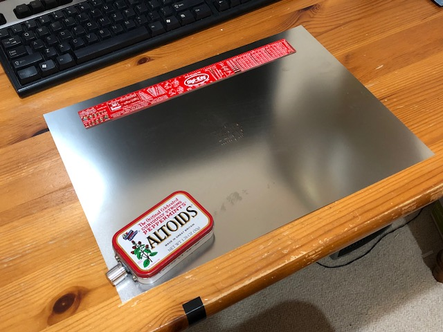
I should make a build guide thread - it might help clear up some of the unknowns and hurdles that many people might have. I am waiting for my order from Mouser to arrive with some of the special parts like the 8-pin board to board header cable. I am about to embark on a MELF build to satisfy my curiosity that this will all work. I happen to order the solder paste stencil. It's pretty comical how big of a sheet of stainless shim stock they put it on without trimming it down... 15in (380mm) x 11in (280mm) for a tiny 30mm x 40mm board. I am not sure if I should just take tin snips to it because it leaves ragged edges. Those little holes in the middle are the stencil patterns ")
Attachments

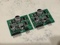
I built up the original SMT daughterboards with the MELF resistors. They are much trickier to install than rectangular chip resistors. My biggest problem was forgetting to use the corrected schematic. The correct assignment is R2=33k and R3=10k. The other thing I learned was that the standard (non SMT) header pins cannot be reflow soldered as the plastic part melts. They must be done manually with an iron. Getting through all that, the amp works fine and is singing now with the MELFs. I am running 10k/1k for feedback so now at 20dB gain vs 22dB previously.
The solder paste and hot plate method worked very well and neatly for the MELFs.

The solder paste and hot plate method worked very well and neatly for the MELFs.
Attachments
Sorry I wasn’t clear, the TH schematic and silkscreen is fine. That’s what you have above.
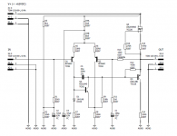
The MELF SMT silkscreen needs to go with this schematic:
Note that schematics are not the same between different daughterboards. The images I have should be labeled with the board type. You will notice TO92 designations on the LTP.
The MELF SMT silkscreen needs to go with this schematic:
Note that schematics are not the same between different daughterboards. The images I have should be labeled with the board type. You will notice TO92 designations on the LTP.
I am starting to pack the items for GB2/GB3. Please review this list and make sure it is complete. If anyone has a request for me to ship to an address that is different than the address associated with the PayPal invoice, please let me know via PM.
Thanks and happy new year everyone!
X
Thanks and happy new year everyone!
X
GB #2 Closed
Thimios - 1 set SMT, Paid
Pinnocchio - 1 set SMT, Paid
Mituisho - 1 set SMT, Paid
Alurudin - 1 set TH, Paid
*muthumuthiah - 3 sets all TH, ship all with order from GB #1, Paid (special address?)
jwjarch - 1 set TH, Paid
jwjarch - 1 set of TH daughterboards only, Paid
jwjarch - 1 set SMT 0805/1206 (shipment to be combined with above), Paid
briansz - 2 set TH, Paid
steefdebruijn - 2 sets TH + spare set SMT daughterboards, Paid
jmc207 - 2 sets: 1 TH and 1 SMT; +1 spare set TH daughterboards, Paid
marcus22ch - 2 sets SMT, Paid
vanofmonks - 1 set TH, Paid
pfisl - 1 set TH, Paid
neoinc - 1 set TH, Paid
redarc12 - 1 set of TH daughterboards only, Paid
gtose - 1 set SMT 0805/1206 version, Paid
Vunce - 1 set TH plus 1 spare set of TH daughterboards, Paid
Malvin - 1 set SMT 0805/1206, Paid
arthur - 4 sets, 2 TH & 2 SMT, Paid
cowneko - 1 set SMT 0805/1206, plus DZT5401 & fjv1845 set, Paid
---- List for GB #3 - Still Open ----
*nania - 1 set SMT, Invoice sent - need payment please
Pierre QuiRoule, 1 set TH, Paid
jugi63, 1 set TH, Paid
bk856er, 1 set TH, Paid
ft0601, qnty 2 complete sets TH, Paid
I happen to order the solder paste stencil.
Ha, thats a pretty awesome, I wonder how much extra they had to pay for shipping on that. I assuming it couldn't be shipped rolled. In the past I've had good luck with OSH Stencils. I've ordered their laser cut polyimide, so not as durable as your typical metal stencil, but good for a pasting a handful of boards.
For this build, I'll probably use a fancy new solder paste dispenser I bought in on via Kickstarter (I-EXTRUDER smart Solder Paste and Fluids dispenser for PCBs by Artline International —Kickstarter). I haven't had a chance to use it yet.
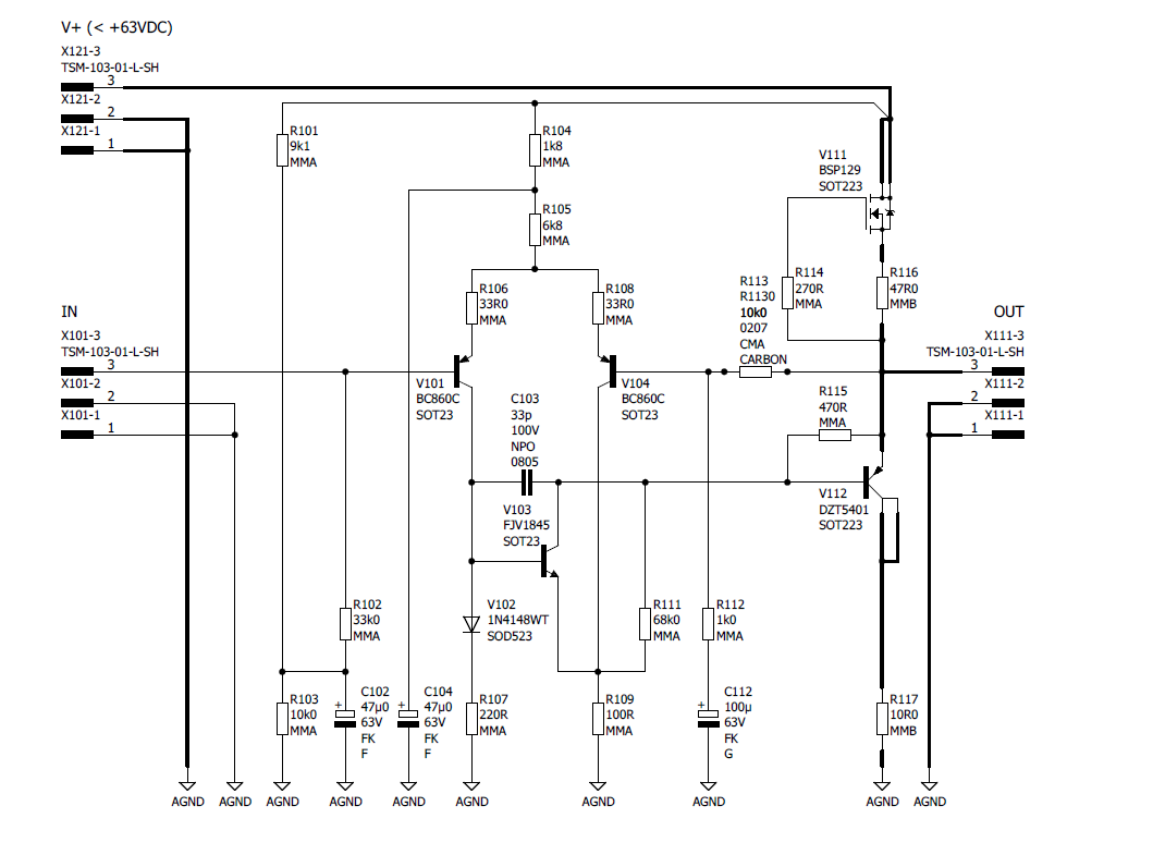
The new SMT 0805/1206 daughterboard has been verified to work.
Those look great! For the SMD chip resistor version will there be an updated BOM specifying the footprint for each resistor?
Also, I'm guessing it may be mentioned somewhere in this thread or the original build thread, but what is the recommended power supply or are there any guidelines for sizing the power supply? I'm assuming the CLC filter board is intended to be used in with a SMPS? Any recommended power bricks?
Thanks for all of your (and JPS64's) work on this and Happy New Year!
Greg
This is the actual DC-DC step up I am using now. It can go to 60v.
400W DC DC Step up Boost Converter Constant Current Power Supply Module LED Driver Step Up Voltage Module-in Inverters & Converters from Home Improvement on Aliexpress.com | Alibaba Group
I set it for about 4v above 48Vdc or 52V. Then the cap mx drops 4v for 48Vdc. You could run a bit higher if you wanted just check thermal.
Then use any 12v, 19v, or 24v laptop smps or small 12v smps wall wart for external HDD.
Like this works well:
inShareplus 12V LED Strip Power Supply 2A 24W, Wall Mounted 12V Switching Power Supply, 110V to 12 Power Supply for LED Strip Light with 5.5/2.1 DC Female Barrel Connector to Screw Adapter - - Amazon.com
I am not using the CLC filter. It’s not needed with how clean my supplies are. If you use it make sure the cap is not too big or the wallwart will auto protect upon turn on. That’s why the cap Mx is there after the step up. To slow ramp it up and not shut down when charging the CRCRC.
Maybe use 470uF for CLC. That should be ok.
Last edited:
Maybe JPS64 can tell us if the BOM for the 0805/1206 version is in the Datafile package. I can’t seem to find it. I worked off the schematic. One of the first things to do is print out a large image of the top PCB components picture. The go through the schematic and label part values. Then work from that to do the pick and place with the chips.
For this build, I'll probably use a fancy new solder paste dispenser I bought in on via Kickstarter (I-EXTRUDER smart Solder Paste and Fluids dispenser for PCBs by Artline International —Kickstarter). I haven't had a chance to use it yet.
I just watched the video, that thing is really cool. Sure beats using a manual syringe. If I ever do more complex SMT prototyping this could be really handy.
A more conventional one for production is available for $90 here:
Free Shipping NEW YDL 2000 Semi automatic Glue Dispenser/ plastic injection machine AB/UV/ SMT Solder Paste/Liquid Controller-in Plastic Welders from Home Improvement on Aliexpress.com | Alibaba Group
- Home
- Group Buys
- AKSA's Lender Preamp with 40Vpp Ouput GB