Hello all,
Recently been fascinated by differential amplifiers. Mainly due to getting a transformer where I underestimated the voltage ratings. So my solution is to go differential.
This is an idea based on Edmond Stuart's MCP / PMP amplifiers.
Frent-end
Also incorporating Bob Cordell's fix for the Cascoded Enhanced VAS (100p caps)
http://www.diyaudio.com/forums/soli...lls-power-amplifier-book-324.html#post3508549
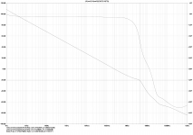
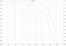
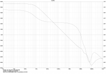
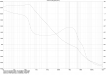
This amplifier has a low ULGF for the main loop and appears to behave well. Has flat THD almost to clipping. The THD peaks at the transition from class A to B.
Have attached some loop gain plots. The first is for the global feedback loop, the second is for the TMC loop around the OPS and the third is for the CMCL.
This amp works in simulation, however, I wonder about what DC servos are required. I think only a common mode servo is required?
Can't help but think that, due to differential nature of this amplifier, there may be some clever distortion cancelling mechanisms that could be taken advantage of.
The OPS biasing will be taken care of by two LT1166 ICs. Pin 2 unused")
Take care,
Paul
Edit: Not to forget BesPavs creation The β24 fully-differential power amplifier
Recently been fascinated by differential amplifiers. Mainly due to getting a transformer where I underestimated the voltage ratings. So my solution is to go differential.
This is an idea based on Edmond Stuart's MCP / PMP amplifiers.
Frent-end
Also incorporating Bob Cordell's fix for the Cascoded Enhanced VAS (100p caps)
http://www.diyaudio.com/forums/soli...lls-power-amplifier-book-324.html#post3508549
This amplifier has a low ULGF for the main loop and appears to behave well. Has flat THD almost to clipping. The THD peaks at the transition from class A to B.
Have attached some loop gain plots. The first is for the global feedback loop, the second is for the TMC loop around the OPS and the third is for the CMCL.
This amp works in simulation, however, I wonder about what DC servos are required. I think only a common mode servo is required?
Can't help but think that, due to differential nature of this amplifier, there may be some clever distortion cancelling mechanisms that could be taken advantage of.
The OPS biasing will be taken care of by two LT1166 ICs. Pin 2 unused
Take care,
Paul
Edit: Not to forget BesPavs creation The β24 fully-differential power amplifier
Attachments
-
 Differential CMCL LG Global.png178.5 KB · Views: 1,264
 -
Differential CMCL 4.asc27.3 KB · Views: 103
-
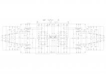
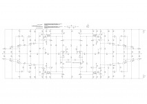 Differential CMCL 4 Schematic.png148.6 KB · Views: 1,266
 -
 Differential CMCL 4 CL.png194.5 KB · Views: 1,162
 -
 Differential CMCL 4 CMCL LG.png198.2 KB · Views: 1,118
 -
 Differential CMCL 4 LG TMC.png179.7 KB · Views: 1,147
Last edited:
Hi
It looks like a very good and robust design.
Comments: I would have used a so called BJT H-Bridge IPS instead of the diff JFET IPS, or even better an IPS with two H Bridge IPS's as an VFA instead of a CFA IPS.
BTW: The IPS you have looks more like a JC thing than something Edmond would design.
I think that you would need 3 DC servos using your IPS and no servos using a VFA IPS.
Yours
Reodor
.......
This amp works in simulation, however, I wonder about what DC servos are required. I think only a common mode servo is required?
..........
In my adventure with a fully differential, crazy discrete, power amp with CM loops HERE I found it useful to use a DC servo for each input. Even though the speaker does not connect to the center potential, (GND for bipolar power supply) each output DC should remain at the center potential so that the two outputs clip at the same time or a DC component will be left across the speaker......which is bad

Last edited:
The OPS biasing will be taken care of by two LT1166 ICs. Pin 2 unused
[/url]
Hi
BTW.:
I see no reason for using LT1166 as Bias spreader for a BJT OPS.
Yours
Reodor
Not to forget BesPavs creation
Hello, Paul!
Not so mine, but i have an opinion.
AMB Laboratories DIY Audio • View topic - Understanding Beta
It's OLG could be seen there:
AMB Laboratories DIY Audio • View topic - Simulating Beta24
Not so much as it could, but note relatively high-frequency pole, resulting in almost flat feedback depth around all audioband.
So THD at 1 and 20 kHz mostly the same.
Also note points of CMFB connection.
Thank you for all your comments.
Hi Reodor,
Regarding the IPS choice. It is a trade off. Understand that using a BJT input stage would result in lower THD due to the higher transconductance. But I like the elegance of the floating JFet input. The other issue with JFets is obtaining them as most are obsolete now. Linear Systems make some but they are expensive. Ideally I need matched sets or a large enough quantity to match them myself. Arguments for going for the BJT CFA... Have to re-simulate the VFA suggestion but past experiments showed little improvement.
AS for the choice of the possibly using the LT1166 is that I would like to use a non standard biasing scheme . Like to try and make something different to the norm. Open to suggestions.
Also, instead of using three servos, could I use one common mode and one differential mode?
Lastly, the ideas taken from Edmond are the CMCL loop configuration and the use of DTMC.
CBS240,
Understand your point about symmetrical clipping. (Didn't think of that.) This would suggest that the differential mode DC servo would not be a good idea as it does not reference ground. That is an impressively complex amp you link to
BesPav,
Apologies I thought the beta24 was your creation.
Started reading the links then they started to fail to connect here at work. Will try again at home later.
Assuming you mean the Jfet servo creation when you mention the CMFB connection. This would suggest a common mode servo is required. Wonder is I could connect a servo to CMCL points on my amp instead of connecting them to 0V which should do the same job?
Oh, and the Beat 24 is almost an order of magnitude faster than this creation... This one currently cannot go that fast.
Take care
Paul
IF you can get your hands of those complimentary JFets, by any means, use them, and in exactly the fashion you have planned.[...]
Regarding the IPS choice. It is a trade off. Understand that using a BJT input stage would result in lower THD due to the higher transconductance. [...]
In my experience they are vastly superior to a BJT input.
Look up Pavel Macura's findings about them in an input stage.
Distortion in JFET input stage circuits
And if you go for high feedback, use less degeneration, i.e. smaller source resistors and especially a much smaller R7.
And don't chase for ultimately lowest THD, it doesn't pay off vs. complexity and stability. Don't trust the simulations. Build it.
Hi Sottomano,
The Pavel Macura link makes interesting reading. Seems as though lower value degeneration and R7 resistors are the way to go. Although, I have currently tuned the compensation for good performance into reactive loads.
Will try scaling the compensation for R7 = 100R. Have a later version simulated at home with R7 = 200R. Will post it later. What in your opinion is a good value of R7 to go for?
Agree, THD performance is secondary. I go for stability first and foremost. No good having an amp that bursts into oscillation under certain conditions. More than happy with current THD levels of around 0.001% at 20KHz. It was a surprise when I looked. It's more of a curiosity once I have the loops stable.
Paul
Assuming you mean the Jfet servo creation when you mention the CMFB connection.
Just check where CMFB reverses.
To the emitters of the VAS.
Oh, and the Beat 24 is almost an order of magnitude faster than this creation... This one currently cannot go that fast.
That’s not a bug, that’s a feature.
Why you doesn’t change compensation for your amp?
I’m truly prefer to have ~60 dB constant feedback depth up to 80 kHz with a UGF around 3-5 MHz.
PS. Lower R at the bases of last OPS devices. With such a value they could run to C-class at heavy load.
Hi
or even better an IPS with two H Bridge IPS's as an VFA instead of a CFA IPS.
...
and no servos using a VFA IPS.
Yours
Reodor
Have thrown together the version suggested by Reodor. It has the addition of a feedback baker clamp as this amp will be run off two independent PSUs. The front end one being regulated the output stage one will be unregulated.
Would like to determine whether Reodor is correct as to whether any DC Servos are necessary. Or whether I should go with CBS240s suggestion.
That’s not a bug, that’s a feature.
Why you doesn’t change compensation for your amp?
I’m truly prefer to have ~60 dB constant feedback depth up to 80 kHz with a UGF around 3-5 MHz.
PS. Lower R at the bases of last OPS devices. With such a value they could run to C-class at heavy load.
The speed at the Beta 24 amp is impressive. Think my amp is slow in comparison because of the CMCL VAS.
The compensation needs work. The main loop has a ULGF of 265KHz. My problem has been the need to add some lead compensation. I.e. capacitor across feedback resistor. But being a CFA this wasn't an option. Maybe this VFA version has some potential due to this being an option.
Flat feedback of 60dB up to 20 kHz is impressive.
Paul
Attachments
Hi
Yes that is close to what I mean.
My suggestion is that you don't connect the first BJT Collectors in the "Diamond" to the E of the second BJT's in the "Diamond"
It is better if you add 4 more CB BJT's with the B connected to the same point as the B of the second BJT's in the "Diamond" and connect the C of the first BJT's to the E of those transistors.
In my opinion it's a lot better to design an Amp that is stable and has very low THD+N without the need for a lot of unnecessary compensation.
BTW: I don't use LTSpice so I can't read your files, I'm just seing the low resolution pictures that you have uploaded.
Cheers
Reodor
Hi Paul,
it is impressive, how one can expolit canceling mechanisms in symmetrical circuits in order to get good performance. As in real life, there are so many completely different ways one can go ...
As outsider (do not understand the subleties of these circuits), I only have one concern: Could you please describe a little bit, how you measure your loop gains, when you discuss such an issue next time?
Kind regards,
Matthias
Could you please describe a little bit, how you measure your loop gains, when you discuss such an issue next time?
Short inputs to ground.
Place two AC sources in series with feedback after loading an amp.
Draw a plot for an equation shown.

Keep in mind, this is cheater’s method. It provides adequate results with low-output impedance output stage (say, any kind of follower) and high-input impedance input stage (not inverting input of current feedback opamp).
Maybe this VFA version has some potential due to this being an option.
There are one underestimated issue.
OPS devices will exhibit beta drop under high load. Being differential this amp will see half a load resistance at each output. So, while SOA doesn’t an issue (due to half a voltage) you need to add additional OPS devices for sharing current.

Also lower supply voltage drops OPS bandwidth at high output voltage levels.
Being conservative, i’ll suggest one OPS device for 5 A of output current.
MOSFET’s doesn’t have theese effects and preferrable in differential OPS’es.
Last edited:
Or use large current hogs like these...
For pumping input capacitance of a real beasts like these:
http://ixapps.ixys.com/DataSheet/DS100401B(IXTK-TX120P20T).pdf
http://ixapps.ixys.com/DataSheet/DS99980(IXTK140N30P)).pdf
Or put those beasts in a tracking cascode...
Your hogs a little bit slowy, this will limit us in reaching good feedback depth.
Slow they certainly are, Ccb is huge!! , will require essentially a power amp driver!.
I have used unconventional output transistors in the past Here
And at the present, Here. Working on cobbling together an offline converter for this project.
I think it will be fun to try an amp using these. I'm thinking a HEC mosfet power stage, and using these in current feedback configuration. Future project for sure.
, will require essentially a power amp driver!. I have used unconventional output transistors in the past Here
And at the present, Here. Working on cobbling together an offline converter for this project.
I think it will be fun to try an amp using these. I'm thinking a HEC mosfet power stage, and using these in current feedback configuration. Future project for sure.
...I only have one concern: Could you please describe a little bit, how you measure your loop...
If I may answer for Paul since he seems to be on holiday.
...Keep in mind, this is cheater’s method...
Paul does not use this method to measure his loops, I am pretty sure.
I made, and sent him a copy of, an LTSpice "virtual transformer" that extracts the common mode and differential mode.
It uses controlled sources so it is ideal, works from DC to unlimited frequency.
Tian probes can be inserted in to the transformer.
When the inputs and outputs are placed correctly then it can be used to measure both common mode and differential mode Return Ratio.
This method does not have the limitations of the "cheater" method.
I also made and sent a "double" Tian probe so that both loops could be checked simultaneously, it's tedious otherwise to have to move the probe every time.
Matthias, is this what you wanted to know?
Best wishes
David
Last edited:
"virtual transformer" that extracts the common mode and differential mode.
This method does not have the limitations of the "cheater" method.
Best wishes
David
Yes that's the right way to do it.
I'm using a Balun when I analyse differential circuits.
Happy New Year
Reodor
...input capacitance of a real beasts like these:
http://ixapps.ixys.com/DataSheet/DS100401B(IXTK-TX120P20T).pdf
http://ixapps.ixys.com/DataSheet/DS99980(IXTK140N30P)).pdf
Hi Pav
I checked the IXYS brochure and found the devices with the lowest capacitance per amp of useful current capacity.
Turned out to be better to parallel several smaller but lower capacitance devices.
Also better thermally, and N and P devices were closer to complementary.
I made VDMOS models with all the latest enhancements (sub-threshold conductance was modeled properly, non-linear capacitance etc)
Toni (ASTX) used the models then built an amp, said the simulation was very close.
He has the details in one of his threads, should be easy to find, search for IXYS.
Best wishes
David
Last edited:
- Status
- This old topic is closed. If you want to reopen this topic, contact a moderator using the "Report Post" button.
- Home
- Amplifiers
- Solid State
- Fully Differential Amplifier With CMCL