Hi everybody! ")
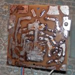
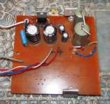
I've made my own PCB for stereo LM1875 gainclone. I've soldered only one channel for check if it works fine. Later I decided I want compact case and now that nesting of components is not very practical because of heatsinks which will take additional place in a case.
I now I should to think about this earlier, but...
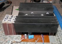
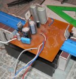
I think about 2 options of heatsink placement. In both cases I have to lengthen my chipamp legs with wire. Shall I have any problems because of it? For example oscillation or noise or something like that?
PS I know about unwashed rosin. I shall have washed my PCB after I have all components soldered.
I've made my own PCB for stereo LM1875 gainclone. I've soldered only one channel for check if it works fine. Later I decided I want compact case and now that nesting of components is not very practical because of heatsinks which will take additional place in a case.
I now I should to think about this earlier, but...
I think about 2 options of heatsink placement. In both cases I have to lengthen my chipamp legs with wire. Shall I have any problems because of it? For example oscillation or noise or something like that?
PS I know about unwashed rosin. I shall have washed my PCB after I have all components soldered.
Attachments
Welcome to diyAudio
It is possible you might introduce problems... these things are hard to predict though.
You should add a single small electrolytic cap of say 10uF between the two supply pins of the chip soldering the cap directly to the pins of the IC. That will help maintain stability.
Keep the main output wire as far away as possible from the wires to the input pins. This will help avoid any capacitive coupling between them.
May be 0,1 uF ceramic capacitor will fit better? The datasheet recommends to use them for stability.electrolytic cap of say 10uF between the two supply pins of the chip
Till now I haven't got any suitable case.
And I have one more option. I can cut my board in half and I'll get two mono amplifiers.
Cut with a saw or dremel.
File with a - file?
File Stanley 022464 File Set includes 1/2 Round/ Flat/ 3 Square (3 Pieces): Amazon.co.uk: DIY & Tools
Saw HDX 2-in-1 Mini Hacksaw with PVC Cable Saw-76-144-112 - The Home Depot
Dremel Products | Dremel Shop
File with a - file?
File Stanley 022464 File Set includes 1/2 Round/ Flat/ 3 Square (3 Pieces): Amazon.co.uk: DIY & Tools
Saw HDX 2-in-1 Mini Hacksaw with PVC Cable Saw-76-144-112 - The Home Depot
Dremel Products | Dremel Shop
The extension of the legs is one way, hacking off the board is another (well, there might be some who see that differently though) but I would like to suggest yet another which avoids any electrical problems. You could mount the IC to an L-shaped aluminium profile or aluminium block and mount the heatsink on it. The heat transfer isn't as good as the IC directly mounted on the heatsink but with a decent size the loss in heat dissipation can be neglected, the big contact surface helps there.
Just in case you didn't understand that, again short and simple:
Put the IC on a big L-shaped aluminium part or aluminium block. Screw the heatsink/cooler onto the Aluminium part. The L-profile should be wide and thick and don't forget the thermal conductive paste.
Just in case you didn't understand that, again short and simple:
Put the IC on a big L-shaped aluminium part or aluminium block. Screw the heatsink/cooler onto the Aluminium part. The L-profile should be wide and thick and don't forget the thermal conductive paste.
Put the IC on a big L-shaped aluminium part or aluminium block.
Yes, this option is probably the most optimal. The only thing I shall have to find a thick aluminium bar and accurately adjust an additional mounting of a heatsink.
Thank you for your advice
Yes, this option is probably the most optimal. The only thing I shall have to find a thick aluminium bar and accurately adjust an additional mounting of a heatsink.
A piece of square stock (i.e. aluminum bar with a square cross-section) should work. Just make sure the faces that attach to the chip and heat sink are smooth. Also use an insulating pad (SilPad or mica) and shoulder washer (a basic TO-220 mounting kit will do) between the chip and the heat sink as the back of the chip is connected to the negative supply (VEE).
Tom
- Status
- This old topic is closed. If you want to reopen this topic, contact a moderator using the "Report Post" button.
- Home
- Amplifiers
- Chip Amps
- Can I lengthen legs of chipamp?