Dear Niffy, glad you had fun, counted on British humor.
I was talking about the earth because considering the earth + sun motion alone, Mr. Tolomeo remains fully valid (in fact, it allowed considerable accuracy in calculations) and nobody could say who is turning around the other, and the same is with our dear old disks (rotating cartridge: good for another thread)
I would really like to have your knowledge and your certainties, but I have only doubts (attachment - sorry in Italian) and your explanation - extremely convincing - is not enough to leave them behind. Still thinking that with the stylus drag (along pivot axis, or orthogonal to the rail of linears) at best could move just the baerwalds (relevant offset), not the linear ones, nor the PLTs. The 6 milligrams of side force you are talking about, do not move a precision mechanical scale (mine stops at 20), certainly not an arm (cable + bearings +damping + etc).
That's why I built that arm meticulously: going against known problems I did not want to have any doubt that they could derive from a rough construction. They certainly came from design, both in the syrinx and the next, but can't find where the problem is, because the second contradicts the hypotheses on the first.
I did not understand it during design process, and no one much more educated than me noted. We all focused on geometry and skating. Well, geometry is accurate, and nothing is more immune to the skating of a standing arm. Mission accomplished!
thank you again for your precious attention - carlo
PS for syrinx's bearings I often consulted your really interesting thread. Why so many are concerned about limiting friction between wheels and rail? a wheel rolls, does not slip; worst, when slipping sometimes may not overcome the viscous friction of the spheres at the start
Attachments
Centripetal acceleration...
Centripetal acceleration will have absolutely no effect on the stylus/groove interface or any other aspects of record replay.
Mr. Newton is still happy.
Niffy
Yes, absolutely correct.
Ray K
Hi Carlo,
It's funny that you mention the flat Earth. Many people believe that the Earth is flat because locally it looks flat. This is because the Earth is very big and we are very small. Likewise, to the very small stylus contact point the large diameter curve of the groove looks locally straight.
With an unmodulated groove (for instance the lead-in groove) the groove walls are parallel to the motion of the record. There is no side force acting on the stylus and thus no stylus movement. (ok there is the small force and movement due to the pitch of the groove)
With the run-out groove the groove is angled relative to the motion of the record. This causes a force acting from the right that moves the stylus to the left.
With a modulated groove the angle of the groove changes constantly causing the stylus to move back and forth.
The curve of the groove has no effect other than that the right hand wall of the groove moves slightly faster than the left. Even at the very innermost groove (where the difference is greatest) the difference in speed is less than 0.01%. You may think that this will result in a very slightly different drag on the two sides of the stylus. However stylus drag is calculated as VTF multiplied by the coefficient of friction. The drag is independent of velocity so it will be even. When groove modulation is added into the mix the rapidly changing forces and speed completely swamps the small velocity difference.
Although the motion of the record is circular the instantaneous motion of the small section of the groove in contact with the stylus is, to all intents and purpose, linear. When I say linear I mean it. At the outside of the record the curvature of the groove over the contact width of the stylus is about the same as the curvature of the earth over 300m.
Centripetal acceleration.
A particle sitting on the outer edge of a record and revolving with it will indeed experience a radial acceleration of about 1.83m/s^ 2. The outer groove of the record will also see this acceleration. As the record is a robust solid it will stay in one piece and there will be no outwards movement and thus no outwards force. Unlike the particle the stylus does not revolve with the record but instead remains stationary above it and so it does not experience any radial acceleration.
Centripetal acceleration will have absolutely no effect on the stylus/groove interface or any other aspects of record replay.
Mr. Newton is still happy.
Niffy
Excellent points. I am learning something as well.
Hi Carlo,
You asked, "Why so many are concerned about limiting friction between wheels and rail?"
The answer is, I don't know why. You are completely correct that the wheels roll and don't slide. For lateral motion in an LT arm the coefficient of friction between wheel and rail is completely irrelevant. What is important is rolling resistance. Rolling resistance can be reduced by making both the wheels and rail out of the hardest material possible, mine are both tungsten carbide. Also increasing the diameter of the wheels can help to reduce rolling resistance. A good analogy is a push bike's tyres. It is much easier to pedal on a bicycle with very hard tyres. Cycling on soft tyres is hard work. For a tangential tracking pivoted arm that has variable effective length, like the syrinx, looking at the bearings of a successful linear tracking arm is a good starting point.
In my arm the friction between wheel and rail is important as vertical pivoting is achieved by the sliding of the wheels on the rail. This friction also supplies the damping that helps to control vertical movement/resonance.
Niffy
I want to know if anyone have built a Naim ARO "Clone" and are willing to share drawings with us")
You're off topic and probably on the wrong thread. No clone here but you can look at the blue prints.
homeworks
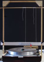
This weekend i've started the tests of post # 1548
The goal is to convert the work of the tracking force at 0 offset into the potential energy of a pendulum. (photos). In spite of a raw aspect, the mock up can be set up accurately: Positioning, VTF and VTA are adjustable. Of course mass and length of pendulum must be checked carefully.
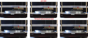
Pre test: the mass was pulled with weights corresponding to the values indicated for VTF by theory. Values calculated from angular displacement were not so bad considering pulley, frictions, misreadings etc.
Theta angle = 0.5 gr> 1,0° -- 1.0 gr> 1,9° -- 2.0 gr> 3,3° - Linear dispacement = 0.5 gr> 7mm -- 1.0 gr> 13mm -- 2.0 gr> 21mm
Test conditions: really common -
medium mass platter (2.7kg) cheap AT95 cartridge with VTF 2.0 gr; average classic orchestra musical content, with no peaks. - 200mm circle track -
Pendulum Length (constraint-CW) = 0,4 m - suspended Mass = 0,041 kg ( mass compensated to the VTF change)
What happens: the stylus advances until skipping, then goes back to catch another groove and so on: the measure therefore oscillates around the maximum. Multiple measures are needed
How it works: as hoped, it is a pleasure to finally see with our own eyes these small forces amplified by the pendulum; for example it can be seen even the variation due to a variable musical content.
Measurements: only my direct observations - theta angle + linear displacement (= L sin theta) - so that anyone can calculate what he wants and interpret as he likes. Simple pendulum potential energy formulas were enough for me.
Beyond results that explain some syrinx behaviours, what is "strange" is that advancement seems to change very few with VTF. More: a test on 290 mm circle with VTF 2.0 gave <4mm displacement, 0.5° theta, 50% less that at 200.mm.
tests done: forward advancement:
VTF 1.5 gr theta angle 0.7° - forward displacement 4 mm
VTF 2.0 gr theta angle 1.0° - forward displacement 7 mm
VTF 2,5 gr theta angle 1,3° - forward displacement 9 mm
Hope this helps - Carlo
tests to do: side displacement
all tests will be repeated with 23° offset + 15mm overhang
This weekend i've started the tests of post # 1548
The goal is to convert the work of the tracking force at 0 offset into the potential energy of a pendulum. (photos). In spite of a raw aspect, the mock up can be set up accurately: Positioning, VTF and VTA are adjustable. Of course mass and length of pendulum must be checked carefully.
Pre test: the mass was pulled with weights corresponding to the values indicated for VTF by theory. Values calculated from angular displacement were not so bad considering pulley, frictions, misreadings etc.
Theta angle = 0.5 gr> 1,0° -- 1.0 gr> 1,9° -- 2.0 gr> 3,3° - Linear dispacement = 0.5 gr> 7mm -- 1.0 gr> 13mm -- 2.0 gr> 21mm
Test conditions: really common -
medium mass platter (2.7kg) cheap AT95 cartridge with VTF 2.0 gr; average classic orchestra musical content, with no peaks. - 200mm circle track -
Pendulum Length (constraint-CW) = 0,4 m - suspended Mass = 0,041 kg ( mass compensated to the VTF change)
What happens: the stylus advances until skipping, then goes back to catch another groove and so on: the measure therefore oscillates around the maximum. Multiple measures are needed
How it works: as hoped, it is a pleasure to finally see with our own eyes these small forces amplified by the pendulum; for example it can be seen even the variation due to a variable musical content.
Measurements: only my direct observations - theta angle + linear displacement (= L sin theta) - so that anyone can calculate what he wants and interpret as he likes. Simple pendulum potential energy formulas were enough for me.
Beyond results that explain some syrinx behaviours, what is "strange" is that advancement seems to change very few with VTF. More: a test on 290 mm circle with VTF 2.0 gave <4mm displacement, 0.5° theta, 50% less that at 200.mm.
tests done: forward advancement:
VTF 1.5 gr theta angle 0.7° - forward displacement 4 mm
VTF 2.0 gr theta angle 1.0° - forward displacement 7 mm
VTF 2,5 gr theta angle 1,3° - forward displacement 9 mm
Hope this helps - Carlo
tests to do: side displacement
all tests will be repeated with 23° offset + 15mm overhang
Attachments
Hi Carlo,
Interesting rig. It's reminiscent of the rig I built to test side force due to bearing friction. I had it easy as I was just testing static friction. Trying to measure the dynamic friction between stylus and record is much more difficult.
I believe that there is a problem with the rig as it is at the moment. The pendulum swings forwards until the stylus skips then swings back and starts the cycle again setting up an oscillation. Due to the length of the pendulum this oscillation will have a natural frequency of about 1.3hz. With a record with a constant level of modulation the stylus drag would be constant, the pendulum should ideally swing forwards to a point and remain in the same position without skipping. As your rig has little lateral movement the stylus will eventually skip due to side force but this should take quite a few revolutions of the platter.
The tests that were performed to determine the coefficients of friction between stylus and record that I use were carried out using strain gauges, similar to those in your digital scales, attached to a more conventional type of arm. (Unfortunately I cannot remember who carried out these tests and can't supply the references). The advantage of this type of test rig is that the cartridge is constrained as it would be in an actual arm so oscillations wouldn't be a problem.
I think you can improve your rig to eliminate the possible oscillation problem and allow you to get much more consistent results. Keep the rig as it is and reattach the string with the weight but attach it to the other end of the pendulum, the rear end, so it pulls in the opposite direction. Attach it to the upper section so that it doesn't interfere with tracking force. Use a much heavier weight, say 30g. Place this weight on your scales and adjust the height of the scales so that when the slack is taken out of the string the pendulum is vertical. A simple way to adjust the height of the scales would be to sit them on a deck of playing cards. By removing or adding cards the height can be finely tuned. Now repeat your tests. Any stylus drag will show up as a reduction in the weight measured by the scales rather than as a deflection of the pendulum. The pendulum in this set up will be constrained from moving so the oscillation problem should be eradicated. Also the stylus will remain aligned to the groove in a more realistic manner which may improve the accuracy of the measurement.
You are also planning on measuring side force. I'm still unclear as to what you are attempting to measure with this test. Is it just the amount of force required to make the stylus skip?
Most importantly have fun learning more about tonearm design with your tests.
Niffy
dear Niffy thanks for the interest and advice: if you make me a quick sketch maybe I understand what you mean.
Some clarification:
as I wrote the weight is 0.041 kg, 41 gr - and the length 0.4m, 40cm. (MKS) -
The oscillation (of measures, i said) has nothing to do with the period of the pendulum: simply when the work of the force brings the pendulum to the corresponding height, the stylus can't go further, loses contact and goes back 1 - 2mm (probably not on the same groove). This involves reading errors; at the beginning I used the flash in the photos, then I saw that with a time of 1/10 the average was directly in the picture. When the rig is well aligned tangentially there is no lateral displacement. Possible skip in an adjacent groove is obviously not perceptible to the eye.
Digital strain gauges are certainly the most appropriate solution (that link to those tests could be really precious, pity you do not remember it), but I do what I can and everyone could do in an afternoon, on the famous kitchen table
You will have noticed that I do not speak of forces (without naming them, since now I do not know what I am measuring) but of frontal and lateral displacement and therefore of work. From a first test I find that the second (lateral) is much greater than the first (forward), so I imagine it can hardly be a component of it.
How do you explain the reported anomalies? and values, have you seen them? I hope that my home tests will amuse me as well as other people, but I begin to doubt it.
ciao Carlo
Last edited:
Hi Carlo,
I've done a quick Google search and found quite a few articles about stylus drag. Unfortunately most of these are mainly interested in what effect stylus drag has on platter speed (none IMO) and not on measuring the force itself or the resultant skating force.
A couple of relevant articles are:
Vinyl Asylum: Skating and antiskating (updated) by Klaus
A sentient passage from this article is
"[coefficient of stylus friction] varies with record material and amount of groove modulation. Values were found to be between 0.22 and 0.64 for Shibata at 1.5 g tracking force"
This is particularly interested to me as that is the stylus profile and tracking force that I use.
The article referenced another interesting article by Robert Pardee : Determination of sliding friction between stylus and record groove, JAES 1981, this is more concerned with the effects of lubricating the record surface but appears to contain some pertinent information. He concludes that the coefficient of stylus friction has a range of average values between 0.31 and 0.61.
I'll attempt to knock up diagram illustrating my suggested mods to your rig. I do all of my posts from my mobile which doesn't make picture editing easy.
Niffy
Thanks, I know that of Vynil with the stopping method, but does not convince completely (the motor is disconnected?) Gave values from 04 to 1.
I will look for the others : there so little on this and nothing on the side force, so many words and not even a measure - thats why I am trying.
I forgot: wheels and linear: did not mean the problems of deformation, elasticity or even van der waals forces, only that with a wheel with ball bearings which, among other things, moves very slowly maybe is better to win static friction as soon as possible and lett balls do their job.
the photo with the VTF 2.5 is wrong, I copied twice that of the vtf 2.0 (very similar results)- will be corrected when I place the next test
ciao Carlo
no hurry for the sketch thanks again
Last edited:
The stopping or slowing method can be informative. It is performed with the belt removed (motor disengaged). Ideally the main bearing of the deck used for the test would be of a very low friction type so the platter, with belt removed, takes a long time to slow down. You also need to know the polar moment of inertia of the entire rotating system, (platter, bearing, mat, record, clamp), to a reasonably high accuracy. Spin the platter up by hand then measure the time taken for the platter to slow by a certain amount or to completely stop. For instance, to slow from 45rpm to 33 1/3rpm or from 33 1/3rpm to stationary. The moments that the desired speeds are reached can be obtained using a strobe disk. From this it is easy to calculate the frictional torque of the main bearing. Then repeat the test but lower the stylus onto the record before the platter rotation drops to the higher speed. Then calculate the new frictional torque of stylus and bearing combined. Take one from the other and you have stylus torque alone. Divide this torque by the distance from the stylus to spindle and you have stylus friction drag. As long as the main bearing is low friction this can be very accurate, if the bearing friction is high it tends to swamp the stylus drag. This method has the advantages that you can quickly test on multiple records and at different radii, and the only additional bit of kit required are a strobe disk and stopwatch (assuming you know the polar moment of inertia of your deck)
Niffy
Niffy
yes, really clever: but I can not imagine how to turn a platter to 33 1/3 by hand, or if not to remove the belt without altering the measurement. Then, as you say, it is difficult to calculate the inertia of platter because except rare cases are not, and should not be, homogeneous (the weight at the center is useless, even harmful for bearing). The measures given there are twice what I found, but mine are taken at 0 offset. That's why repeating in Baerwald conditions could interesting.
carlo
carlo
I had to cut my last post short.
The disadvantage of the spin down method is that it can only give an average value over the period of measurement. You can of course perform tests on both lightly and heavily modulated sections in order to set upper and lower averages. For most design purposes this is adequate. The peek levels of stylus drag, due to sudden loud transients, will be higher than this average. Also this test will not give any information on events such as the transition from a loud passage to quiet or vis versa.
Turning the platter to 33 1/3rpm by hand is simple. (belt has to be already removed) Put your strobe disk on the record and illuminate with a suitable light source. Spin the platter by hand so it is spinning just a little faster than 33 1/3rpm. The dots on the strobe will appear to move clockwise. As the platter slows the dots will appear to move slower and slower. At the moment the dots appear to stop you know that the platter is spinning at exactly 33 1/3rpm. Start your stopwatch NOW. As the platter continues to slow the dots will appear to move anti-clockwise faster and faster. When the platter stops rotating stop your stopwatch.
Determining the polar moment of inertia can be tricky. You need a good set of scales to weight the separate components of your platter including the record itself and any record mat. A ruler to measure the components, a calculator and some patience. Some components such as the main bearing can be eliminated from this if necessary as they sit very close to the axis and add little to the overall inertia. It is better if you can include the bearing but not essential.
I used the spin down method when designing and testing my main bearing in order to determine its energy dissipation. It worked perfectly perfectly
Niffy
The stylus drag force could be calculated (theoretically) by measuring the motor current change between the stylus playing and lifted. Power = force x velocity, Power = voltage x current -> ∆F = ∆I / v, where v depends on groove radius.
Not quite. Power = Voltage x Current x Power Factor. Motors have inductive reactance and because of that the current waveform will lag the voltage waveform. The true power consumed by the motor and its load is voltage times the in-phase current, not the total measured current. Power Factor = Cos(θ), where θ is the phase angle between the voltage waveform and the current waveform. To calculate power accurately, you need to know voltage and either know the current and the power factor of the motor as it is driving the load, or use a true power meter. If using a voltmeter and ammeter, you need to separately derive the in-phase current value in order to calculate a true measure of power consumed by the motor and its load.
Ray K
- Home
- Source & Line
- Analogue Source
- Angling for 90° - tangential pivot tonearms