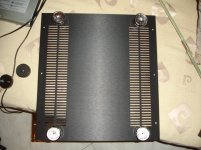
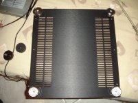
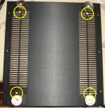
I have placed the feets without mounting under the amp and moved them around for best optic. measured the distance and afterwards checked, if the screws doesn't touch anything inside the amp.
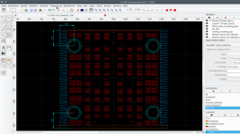
I can send you my cad file from latest amp...
BR, Toni
Thanks Toni,waiting for this.
Bootlace ferrules
Thimios, the build looks good. I see you use bootlace ferrules on the screw connector blocks. I have had more than one bad connection using those. They look very neat, maybe would be better if they are soldered, but I find that the PCB screw connectors with those ferrules are not to be be trusted.
Thimios, the build looks good. I see you use bootlace ferrules on the screw connector blocks. I have had more than one bad connection using those. They look very neat, maybe would be better if they are soldered, but I find that the PCB screw connectors with those ferrules are not to be be trusted.
I have the same doubts but these screw connectors aren't the cheap Chinese garbage!Thimios, the build looks good. I see you use bootlace ferrules on the screw connector blocks. I have had more than one bad connection using those. They look very neat, maybe would be better if they are soldered, but I find that the PCB screw connectors with those ferrules are not to be be trusted.
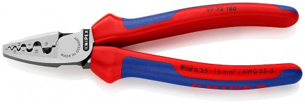
I think I found a cure to my problem. This is the first time that I have seen a crimper like this, it makes more sense now.
0.25-6mm2 AWG24-10 Terminal Crimping Plier Tool Bootlace Ferrule Crimper
0.25-6mm2 AWG24-10 Terminal Crimping Plier Tool Bootlace Ferrule Crimper
Attachments
...
A small pcb for the stand-by led and power button.
Nice variant!
BR, Toni
1 or 2 option?
In a similar project using the original modu case I have mounted the feet using one of the venting holes. see attached picture as example.
BR, Toni
Attachments

Never!... don't give up on the last mile
BR, Toni
Dear Thimios,
looks pretty good!
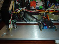
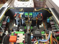
I would do one change: the small signal lines (ribbon cables) route above in the middle of the amplifier. The sharp edges from the steel bottom may destroy the cables.
The signal cables carry only constant DC and speaker output signals decoupled by 4.7k (for DC detection).
BR, Toni

Ribbon cable rearranged !
Attachments
Maximum Thanks Toni!!!!!!!!!!!!!!!!Maximum congratulations!
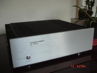
Have fun with your masterpiece!
BR, Toni

Last edited:

- Status
- This old topic is closed. If you want to reopen this topic, contact a moderator using the "Report Post" button.
- Home
- Amplifiers
- Solid State
- SA2015 V-MOSFET Builders