About the Display LTC-2723E, is it possible to use a 4-digit 12 pin cathode alternative?
the only option I found here in Brazil, besides the 12 pin, is this one:
http://www.foryard-led.ru/pdf/fyq-4041gx_hx.pdf
Will it work?
Thanks!
It is not a "plug in" replacement, the pin out is different. If you remote mount the display, you can use it by "translating" the pin out with the interconnect cable.
About the Display LTC-2723E, is it possible to use a 4-digit 12 pin cathode alternative?
the only option I found here in Brazil, besides the 12 pin, is this one:
http://www.foryard-led.ru/pdf/fyq-4041gx_hx.pdf
Will it work?
Thanks!
I too can't acquire the Liteon LTC LED module and have bought a similar China made module which I'm assuming its the same pinout as yours to use time being. I'm in the process of gathering all the parts required for the build at a later time and looks like I've to sort the pin out config to match the pcb pinout.
Its imperative that I achieve getting the board to work flawlessly with all that I've gathered, then swap the LED display for something else or whatever that may suit my liking.
Dear Pyramid,
I have just completed the SG4. Unfortunately the second segment of the display is not working. Initially I have mounted the display via cables so that I can mount it on a front panel and the second digit was not working. I have decided that the problem is somewhere in the cable so mounted a socket on the PCB and mounted the display over it. The problem remains. I am sure that there are no cold solder joints...and the problem is not with the display as well as I've tried 3 different displays all with the same issue.
Will appreciate your input.
Best regards.
p.s. Currently I am feeding the SG4 with 7 volts adapter as I do not have 12v one.
I have just completed the SG4. Unfortunately the second segment of the display is not working. Initially I have mounted the display via cables so that I can mount it on a front panel and the second digit was not working. I have decided that the problem is somewhere in the cable so mounted a socket on the PCB and mounted the display over it. The problem remains. I am sure that there are no cold solder joints...and the problem is not with the display as well as I've tried 3 different displays all with the same issue.
Will appreciate your input.
An externally hosted image should be here but it was not working when we last tested it.
Best regards.
p.s. Currently I am feeding the SG4 with 7 volts adapter as I do not have 12v one.
It looks like digit 2 is partially lit (a lower case "t" is barely visible). The other digits appear correctly, so the 7 segment driver (U3 and R10-R17) are all OK. The display is common cathode and Q2 controls when the second digit is displayed (pin 14 of the display is grounded to enable digit 2). If you temporarily short drain to source on Q2 (or short pin 14 of the display to ground), the second digit will be enabled always and you will see an "8" (the second digit will display "S", "t", "b" & "Y" so all of the segments will be lit). If this happens, then the display is OK and the connection from Q2 to pin14 should be OK.
If you have a scope, look at the gate of Q2; you should see a square wave with a period of 20mS and a positive duty cycle of 25% (digit 2 is on 25% of the time). If you don't have a scope, a DC voltmeter should show ~1.25VDC on Q2 gate. Q2 gate is feed directly from pin 24 of the microprocessor. Check that there are no shorts to ground or open circuits from U1 pin 24-->Q2 gate; from Q2 drain-->display pin 14.
The output op-amp has an 8V regulator for a supply; with 7VDC input, you will only get 5-5.5VDC output to U2 opamp and the output signal may be distorted. You should use 12VDC to power the SG4.
Sinewave Generator in Japan w/100V 50hz
Greetings, I recently found out my job was moving me to Japan for a few years. I have a VPI Scoutmaster 2 (standard 300 rpm motor) that I'd like to take with. I'll be near Tokyo and the main lines are 100V and 50Hz. I'm going to run a good quality transformer to bring the main voltage up to 115V, but I have yet to find a good one that will correct the frequency to 60Hz.
Based on what I read so far, I should be able to build this controller and it will provide me with enough adjustment to correct the 50Hz main frequency to 60Hz. I will most likely build the two phase 60W LM3886TF amp as shown in a different thread.
If I'm correct in my analysis, I will start building away! Any help would be greatly appreciated!
I've also looked into a VPI SDS, but they are becoming quite hard to find. Thanks!
If it were me, I'd use the TDA7492 class D amp :http://www.diyaudio.com/forums/analogue-source/300371-60-wpc-amplifier-diy-turntable-motor-drive-5.html#post4967916
The amp will run much cooler and you can use the R & L channels for 0° and 90°, same configuration as the LM3886 amp. I would also use the Amgis L01-6362 toroid xfmrs for the outputs.
Hi Ralph, first of all, thanks for giving the DIY folk the SG4. The more I study it the more I appreciate the amount of work that you must have put into it.
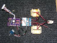
I have cobbled together a dual phase version and it works well. I think I may try driving the transformers with two LM3886 amplifiers though, as I think the little amp is struggling. It will drive the transformers to output 110 volts, but any higher and the amplifier output drops to about 30 volts, so I presume the amp is about at its limits, and it gets a bit warm, I did try it with one transformer and a capacitor for the second phase, no problems.
I am thinking about building another one with headers for the display and outputs, as you can see from my picture one of the display wires has snapped. Cheers, and many thanks, Claxton a.k.a. Rob.
Attachments
If it were me, I'd use the TDA7492 class D amp :http://www.diyaudio.com/forums/analogue-source/300371-60-wpc-amplifier-diy-turntable-motor-drive-5.html#post4967916
The amp will run much cooler and you can use the R & L channels for 0° and 90°, same configuration as the LM3886 amp. I would also use the Amgis L01-6362 toroid xfmrs for the outputs.
Thanks. I like the LM3886 setup. I had a few questions though before I start diving into this project.
- With the two phase configuration, it looks like you drive the VPI motor directly? I've read the threat on optimally driving a VPI motor, but I'm curious if two phase operation is really necessary. I'd like to keep the motor housing stock if possible and wire to a grounded three wire plug. Also, if I run two phase, does the power supply you list in the thread cover the power requirements?
- Will a stereo 10k pot work to reduce the output from the SG4 module? Since I'm not in Japan yet and don't have the 115V step-up transformer in hand, I don't want to hard wire in a voltage divider just yet.
Again, thanks for the assistance. I look forward to the project.
Matt
-
Hi Ralph, first of all, thanks for giving the DIY folk the SG4. The more I study it the more I appreciate the amount of work that you must have put into it.
I have cobbled together a dual phase version and it works well. I think I may try driving the transformers with two LM3886 amplifiers though, as I think the little amp is struggling. It will drive the transformers to output 110 volts, but any higher and the amplifier output drops to about 30 volts, so I presume the amp is about at its limits, and it gets a bit warm, I did try it with one transformer and a capacitor for the second phase, no problems.
I am thinking about building another one with headers for the display and outputs, as you can see from my picture one of the display wires has snapped. Cheers, and many thanks, Claxton a.k.a. Rob.
Hi Bill "Pyramid",
sorry, all credit goes to you! My head is so full of SG4 I don't know what I'm doing. Many thanks Robin
Thanks. I like the LM3886 setup. I had a few questions though before I start diving into this project.
- With the two phase configuration, it looks like you drive the VPI motor directly? I've read the thread on optimally driving a VPI motor, but I'm curious if two phase operation is really necessary. I'd like to keep the motor housing stock if possible and wire to a grounded three wire plug. Also, if I run two phase, does the power supply you list in the thread cover the power requirements?
Hello all, About the VPI motor. I reckon you guys are with a 110V VPI Hurst motor. I'm not sure how its wired up inside the deck or pod, but I've recently come across an issue with Asia Pacific 230V/50hz specific motor. There's a 3Kohm/10W resistor wired in series to the Live to the motor. While its good with direct to wall power, it pose an issue with speed controller (Nigel Speed controller with 80VA step up to 230V, TDA7293 bridged amplifier). What is happening is with the resistor there, which possibly form a current limiter and to slightly reduce the incoming by 10-20V less and less vibration, the speed controller will not start at 45rpm at all. The pulley is seen juddering and stationary. It would start up normally at 33rpm but not at 45rpm select. Removing the 3kohm resistor solved the problem. Hurst datasheet points to direct wiring without any resistance in series for all motors, but VPI put one there. The phase shift capacitor is also different value from the datasheet. I've seen mine with 2ea 0.22uf in series = 0.1uf, another Classic 1 tt with same motor but 0.22uf instead. I reckon I'll have to remove the resistor when my SG4 controller is ready sometime in the near future. Just for info.
Last edited:
Thanks. I like the LM3886 setup. I had a few questions though before I start diving into this project.
- With the two phase configuration, it looks like you drive the VPI motor directly? I've read the threat on optimally driving a VPI motor, but I'm curious if two phase operation is really necessary. I'd like to keep the motor housing stock if possible and wire to a grounded three wire plug. Also, if I run two phase, does the power supply you list in the thread cover the power requirements?
If you power the motor directly with 2 phase (remove the phase cap), it will run smoother and have more torque. I've used the stock 3 pin IEC connector to accomplish this (0° on hot, 90° on neutral and both returns on the ground connection), but it goes against standard wiring compliance and I can't recommend that you do it. If you do, you should add a separate safety ground wire to the case of the SAMA and mark the connector as modified. If you plug a standard IEC cord into the modified socket, nothing will happen as only one phase of the motor is driven so it will not turn, but it also will not be damaged.
- Will a stereo 10k pot work to reduce the output from the SG4 module? Since I'm not in Japan yet and don't have the 115V step-up transformer in hand, I don't want to hard wire in a voltage divider just yet.
Yes.
Hi Bill "Pyramid",
sorry, all credit goes to you! My head is so full of SG4 I don't know what I'm doing. Many thanks Robin
Cheers....

Hello all, About the VPI motor. I reckon you guys are with a 110V VPI Hurst motor. I'm not sure how its wired up inside the deck or pod, but I've recently come across an issue with Asia Pacific 230V/50hz specific motor. There's a 3Kohm/10W resistor wired in series to the Live to the motor. While its good with direct to wall power, it pose an issue with speed controller (Nigel Speed controller with 80VA step up to 230V, TDA7293 bridged amplifier). What is happening is with the resistor there, which possibly form a current limiter and to slightly reduce the incoming by 10-20V less and less vibration, the speed controller will not start at 45rpm at all. The pulley is seen juddering and stationary. It would start up normally at 33rpm but not at 45rpm select. Removing the 3kohm resistor solved the problem. Hurst datasheet points to direct wiring without any resistance in series for all motors, but VPI put one there. The phase shift capacitor is also different value from the datasheet. I've seen mine with 2ea 0.22uf in series = 0.1uf, another Classic 1 tt with same motor but 0.22uf instead. I reckon I'll have to remove the resistor when my SG4 controller is ready sometime in the near future. Just for info.
Thanks for the heads up! Are you sure the motor is designated for 230VAC from Hurst, or is it a 115V motor and the 3K resistor allows it to be used at 230VAC?
You could also start the SG4 in 33 RPM mode and switch to 45RPM (The Eagle/Falcon do this automatically when started in 45 RPM mode).
Thanks for the heads up! Are you sure the motor is designated for 230VAC from Hurst, or is it a 115V motor and the 3K resistor allows it to be used at 230VAC?
You could also start the SG4 in 33 RPM mode and switch to 45RPM (The Eagle/Falcon do this automatically when started in 45 RPM mode).
Hi Bill,
I don't see issue or blame any suitable speed controller but I was surprised the VPI with this motor and resistor posed a problem at 45rpm startup.
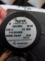
Here's the picture of the motor. This motor is with an old part number. Current/equivalent according to official Hurst data is 3203-007.
No mistake about 3Kohm resistor wired with this.
Attachments
Last edited:
It's not surprising the motor would have trouble starting at 45 RPM (67.5Hz). At 10W, the equivalent motor load is ~5290Ω, so 3K in series would lower the voltage quite a bit. At 45 RPM, the voltage should actually be higher than 230VAC to develop the same torque as 33 RPM (50Hz). Even without the resistor, the motor will not develop rated torque at 45 RPM unless you raise the voltage above 230VAC, due to the increased back EMF generated by the motor at the higher speed.
Which VPI table is the motor used with? I wonder if the resistor was an attempt to lower motor vibrations?
Which VPI table is the motor used with? I wonder if the resistor was an attempt to lower motor vibrations?
It's not surprising the motor would have trouble starting at 45 RPM (67.5Hz). At 10W, the equivalent motor load is ~5290Ω, so 3K in series would lower the voltage quite a bit. At 45 RPM, the voltage should actually be higher than 230VAC to develop the same torque as 33 RPM (50Hz). Even without the resistor, the motor will not develop rated torque at 45 RPM unless you raise the voltage above 230VAC, due to the increased back EMF generated by the motor at the higher speed.
Which VPI table is the motor used with? I wonder if the resistor was an attempt to lower motor vibrations?
Thanks for enlightening me on the matter. So far, I've only seen this motor used on the Asia Pacific VPI Classic 1 (ver 1 & 2). The final version of Classic 1 before it was discontinued (exported here too) is with motor at the rear left corner having an entirely different motor, Hurst 24V/60hz/600rpm/5W/Series AB. Fixed inside the deck is VPI designed 24V fixed speed controller to match the motor.
How does the standby switch work? It looks like it just needs to close momentarily to toggle the on/standby state, is that right?
I have a Thorens TD160 which has a 33/off/45 switch, and I'm trying to imagine how to retain the control but wire something up to work with this device. If I had a 3-position switch that was basically open in the middle position but closed in each of the other positions, how could I use that to generate a pulse at each on/off or off/on transition?
I have a Thorens TD160 which has a 33/off/45 switch, and I'm trying to imagine how to retain the control but wire something up to work with this device. If I had a 3-position switch that was basically open in the middle position but closed in each of the other positions, how could I use that to generate a pulse at each on/off or off/on transition?
How does the standby switch work? It looks like it just needs to close momentarily to toggle the on/standby state, is that right?
I have a Thorens TD160 which has a 33/off/45 switch, and I'm trying to imagine how to retain the control but wire something up to work with this device. If I had a 3-position switch that was basically open in the middle position but closed in each of the other positions, how could I use that to generate a pulse at each on/off or off/on transition?
Yes, the Stby switch is a momentary contact closure to ground to toggle the unit on/off. The UP/DN buttons are also momentary (although when held low, they auto-repeat starting at 5 pulses/Sec and increasing up to 20 pulses/Sec the longer you hold them); the 33/45 switch is SPST latching (33 RPM=Open, 45 RPM=ground).
Doesn't the Thorens switch also move the idler wheel? Why not keep the Thorens switch in the 33 position and use the controls on the SG4 to enable/disable, switch speeds between 33/45 and adjust the speeds (as well as the set up for voltage and phase)?
One could always build a "one-shot" circuit using a 555 timer, a 74122 IC or some combination of logic gates.
- Home
- Source & Line
- Analogue Source
- DIY 4 Phase Sinewave Generator for Turntable Motor Drive