OK, I thought carefully about this and IMO that's geometrically impossible...............I did some research on setting VTA by equalizing the crosstalk..............
Nevertheless, if it apparently works (i.e changing cartridge VTA genuinely affects crosstalk), that demands an explanation. So here goes............... :
Changing SRA affects friction via change of stylus-groove presentation. Changes in friction affects mistracking/mistracing as stylus preferentially rides up one groove wall (due to tracking offset angle). Riding one groove wall effectively invokes crosstalk (45 deg error). Then what one might be doing by tuning VTA for minimal crosstalk is setting stylus attitude for minimal stylus-groove friction?
Azimuth (which genuinely does affect crosstalk) coincidentally affects stylus-groove friction via changes to stylus attitude. So (by finding the sweet spot minimum of harmonic distortion) one might set true stylus azimuth. Rather than coil azimuth (which arises from generator geometry)...........
The whole topic of VTA and azimuth setting tracks is very muddy water, and common wisdom is very often plain wrong.................
LD
Last edited:
Changing SRA affects friction via change of stylus-groove presentation. Changes in friction affects mistracking/mistracing as stylus preferentially rides up one groove wall (due to tracking offset angle). Riding one groove wall effectively invokes crosstalk (45 deg error). Then what one might be doing by tuning VTA for minimal crosstalk is setting stylus attitude for minimal stylus-groove friction?
LD
Wouldn't the stylus-groove presentation for a conical stylus remain essentially constant over a range of SRA?
Ray K
Around 6.5 mm (~1/4") rise of the pivot will give 5° VTA change at a 9" arm.
We must be using different definitions? Assuming the tracking force is the same I don't see how the change is not ~atan(.25/9) = 1.6 degrees.
EDIT - I just checked one setup procedure and that is what they gave.
Last edited:
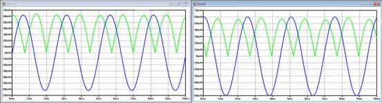
With Scott's Low and High.Wav file, I performed the actions as in the RCA Patent.
The Image below shows in green the modulation of the 4KHz signal.
The difference is rather disappointing, something like 8% between the low and the high setting.
Rather surprising was the fact that the high setting has the lower IM of the two.
The blue signal in the image is the 400Hz in the input signal, just as a reference.
Hans
Attachments
OK, I thought carefully about this and IMO that's geometrically impossible...............
Someone pointed out that raising the arm pivot will require a small change in the overhang (HTA) is this enough to matter? Re-examining some of my data there is a clear repeatable change in crosstalk once you factor out channel balance that points to the same general change as the 400/4K data did.
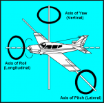
BTW - I wish everyone would stick to pitch, roll, yaw, x, y, z.
")
BTW - I wish everyone would stick to pitch, roll, yaw, x, y, z.
Keep your hands steady and don’t push the pedals
George
Attachments
Yes. For conicals/ sphericals IME this is true. Not only for SRA, but also tracking angle offset error and aspects of azimuth error too. All round, sphericals are far more tolerant of alignment error in terms of stylus-groove friction effect. That's one of the key reasons for otherwise difficult to explain over-performance if one can find a well made spherical stylus on a good cartridge.........Wouldn't the stylus-groove presentation for a conical stylus remain essentially constant over a range of SRA?
Ray K
LD
Last edited:
Ooops I mean 'small and inaudible'.............Just to clarify in principle.............
With sphericals, the incremental effect of misalignment is mostly geometric harmonic distortion only........which is small and audible in the scheme of things for real programme material.
LD
LD
BTW - I wish everyone would stick to pitch, roll, yaw, x, y, z.

I always have trouble with this, may be it's due to my time spent working on radar........... and aircraft/racing cars!
Need to measure intermodulation distortion 4400 Hz.
The program need tow filters 4400 Hz for IMD and 4000 Hz for normalize.
The variation is of 1% order respect to 4000 Hz amplitude in dB. Is important to maintain the 4000 Hz amplitude reference al time for correct measure because the amplitude of 4000 Hz and 4400 Hz will oscillate all time also of the 1% order in dB.
It can also be easily measured with a spectrum analyzer: Audition, Sia Smaart Live.....
Need to measure intermodulation distortion 4400 Hz.
No the 4400Hz and 3600Hz are the AM/FM sidebands (first two). You can not look at just one. The demodulation of the 4k is what you want separated into AM and FM components.
Now I understand. The correct measure would be to include all the intermodulation products.
I have observed that the first two 4400Hz and 3600Hz are the most representative. I have seen with Audition that the following intermodulation products are less representative: 3200 and 4800, 2800 and 5200, 2400 and 5600, ..... more similar among them as they move away from 4000 Hz.
In a spectrum analyzer, observing one of these two sidebands can be a sufficient approximation (like 1 dB). But with all the products, the measurement will be more precise (like 2 dB or more).
Last edited:
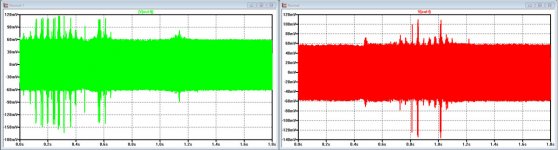
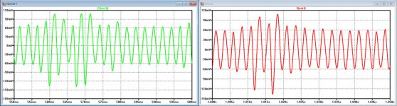
A few more images from Scott's Normal.Wav recording.
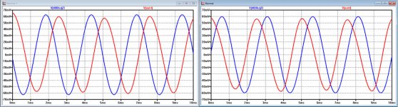
The left image is showing for the Left and Right channel the incoming 400Hz from the LP plus the demodulated 400Hz IM product from the 4KHz before being chopped into positive halves as in the RCA patent.
The 400Hz in blue is out of phase between L and R, confirming vertical modulation of the mono signal, but the IM products in red are in perfectly in phase.
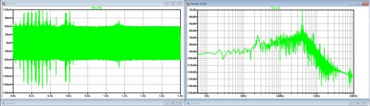
The image to the right is showing again the same demodulated IM signal from the 4KHz, but now for a whole revolution of the LP.
The glitches that are visable, are only there for part of the track and mostly 40msec apart at closer inspection.
Next to the time signal, a 25Hz peak is clearly visible in its spectrum.
Scott, this was the 25Hz that you also noticed, but because these glitches are only there for some part of the track, it doesn't seem to me to be a rumble product coming from your TT.
Could it be that the cutting machine produced this artefact ?
Hans
The left image is showing for the Left and Right channel the incoming 400Hz from the LP plus the demodulated 400Hz IM product from the 4KHz before being chopped into positive halves as in the RCA patent.
The 400Hz in blue is out of phase between L and R, confirming vertical modulation of the mono signal, but the IM products in red are in perfectly in phase.
The image to the right is showing again the same demodulated IM signal from the 4KHz, but now for a whole revolution of the LP.
The glitches that are visable, are only there for part of the track and mostly 40msec apart at closer inspection.
Next to the time signal, a 25Hz peak is clearly visible in its spectrum.
Scott, this was the 25Hz that you also noticed, but because these glitches are only there for some part of the track, it doesn't seem to me to be a rumble product coming from your TT.
Could it be that the cutting machine produced this artefact ?
Hans
Attachments
Here another image showing the demodulated 400Hz signal from the 4Khz, but now for both channels and again for one full LP revolution.
The glitches in this demodulated signal are not at identical moments for L and R, indicating again in the direction of the cutting machine ?
Hans
The glitches in this demodulated signal are not at identical moments for L and R, indicating again in the direction of the cutting machine ?
Hans
Attachments
I have no idea where the 25Hz comes from. I have to apologize for my misunderstanding of the crosstalk test. The left - right - stereo sequence is for shall we say roll and yaw. The RCA test is supposed to be for pitch, I think. I also think the roll and yaw need to be very good before doing the other test or there is too much contaminating information.
- Home
- Source & Line
- Analogue Source
- Test LP group buy