I have a gainclone which i built a few years ago, it has no speaker relays or suchlike, and only makes the slightest "tick" when activating or killing the power..
The "tick" mainly depends on how big are your power filter capacitors.
With linear power supply and filter more than 10.000uF it is a big "tick".
With switching power supply and small filter caps it is a small "tick".
Last edited:
What I've done is to keep the amp muted all the time and only unmute via a raspberry pi GPIO when it starts playing music. If the power goes out the raspi goes out fast and the mute kicks in before the SMPS power ramps down and causes the pop.
Obviously, a dedicated controller that would watch the fault signal and trigger the reset would be better but that would be another project.
Obviously, a dedicated controller that would watch the fault signal and trigger the reset would be better but that would be another project.
I got my 3eaudio tpa3251 board last week, and I tested it.
I am using an unregulated linear PSU which has a toroidal 10A trafo, with taps which provide 22v, 26v and 39v dc outputs when connected to a load. I connected the 22v tap at first, but there was no sound. Then I used the 26v tap. The board says use 24-36vdc.
The sound is better than my tpa3116d2 board. The treble is clearer. Bass is better 'defined'. It sings with a more 'open throat'. Sonically I find it's a better board than 3116d2, and the specs also say so.
Unfortunately, the power output into my 6-ohm bookshelves is low, not even as much as the 3116. At higher volumes, the output shuts for half a second, particularly when the sound peaks. If I reduce the volume, then the Amp keeps playing OK.
I wonder if supply voltage is the only issue, and whether I can correct it by connecting the 39v tap ...
Last edited:
SanjeevM, remember that the in voltage(rail) sets the upper limit for how much power the amp is able to send to the speakers. I use my tpa3116 at 24-25V and you won't be able to play any louder before you increase the voltage in dramatically. Increasing line voltage will also give you less distortion. Depending on the transformer it is sometimes possible to drop the voltage down a bit by connecting a power resistor to it in paralell. Works for testing purposes. I'd suggest you measure the voltage from the powesupply@loud volume with the tpa3251@26V. This way you get a feel for how much the powersupply voltages sags@loads. If it turns out the psu voltage drops with 3V with a 10-20w load, putting a large resistor in paralell with the amp at 36V could work. Of course the psu must be able to handle the increased current with the resistor..
Good idea !! Let me work on that.
I tried out what you said. The tap which gives 26V on load at zero volume drops by 0.4 volts at full (non-clipping) volume. Perhaps the power output isn't really much, so the drop is nominal, I guess. Perhaps the idea of loading the PSU with a power resistor may not be so effective with this trafo.
I re-measured the highest tap. When input voltage is 238.6VAC, the PSU gives me 38.4 volts DC on open circuit, and 36.6v DC when connected to the amp board (my error in prev post). So I guess my PSU is within limits, with this AC input voltage, at least for now. When I play the amp at 80% volume, the voltage drops and the digital MM shows a low of 34.9V on the loudest sounds.
Is it possible (and desirable) to correct this transient voltage drop by using a capacitor bank?
Already the trafo gives out a sharp 'hummm' when switched on for the first time; perhaps the cap bank 4700uf x 8 gets charged up from zero.
Should I get a soft start circuit??
The sound quality is really good at 36.x volts. Much better than at 26.x volts. Much better than the 3116d2. There is no clipping upto 80% volume. I didn't test more because of the bookshelves. Distortion is significantly lower. This board is the best Amp I have hooked up so far !!
Further, I have gone completely linear this time. The 3251 is running on a linear trafo based PSU, and the RPI + Allo-Boss-DAC combo is running on a 10000mAh mobile battery bank. The battery voltage is 5.1V at full charge, but falls to 4.5V when the RPI boots up and the 7 in LCD lights up. There is a low voltage symbol on the screen, but guess that''s OK, since the sound is unaffected!!
Because of this configuration, I have been able to test the modules for DC performance, and I can tell you that I am liking it very much.
To me your cap bank seems a little small. I would make an RC cap bank to lower the ripple a bit and burn off some of that excess voltage. A soft start circuit would be a good idea! On page 6 it says that 36V is typical but 38V is max so perhaps your fine?? http://www.ti.com/lit/ds/symlink/tpa3251.pdf
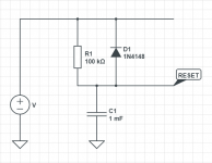
BTW any idea how it works?
It should be slow charge and fast discharge connected to RESET.
Attachments
That wont help the transformer at all.
Suitable Inrush-Current-Limiter.
PVDD: 38V
VAC: 120V
VDC_hv_virtual: VAC*1,414 ~170V
CBulk: 6000uF + 2x2200uF (EVM) ~ 10000uF
Esec = (C*PVDD^2)/2 = (0.01F * 38^2V^2)/2 = 7.22J
CBulk_hc_virt = (Esec*2)/VDC_hv_virtual^2 = (7.22J*2)/170^2V^2 = 500uF (@170Vdc)
Lets assume 600W maximum system power and 90% efficiency for the transformer.
600W/120VAC * 0.9 = 4.5A
For 3A maximum allowable input current (primary) we have:
R = VDC_hv_virtual / I = 170V/3A = 57R
Inrush current limiter needed:
R = 56R
E = 7.2J
I = 4.5A
IRC choosen: SL22 50004
Source: Inrush Current Calculators and How to Select an Inrush Current Limiter
Use in series with primary.
Last edited:
I am planning to use this Soft start board::
EA - Transformer Soft Start, EATSS01 – Eight Audio(R)
The module adds resistors during startup in the AC path to limit inrush current. (That''s what the rep said!).
EA - Transformer Soft Start, EATSS01 – Eight Audio(R)
The module adds resistors during startup in the AC path to limit inrush current. (That''s what the rep said!).
Last edited:
Looks similar in function to what I ordered 220V 1000W Transformer Delay Power Soft Start Protection Board for Amplifier AMP | eBay. I plan to swith out the series resistors with a 60ohm power resistor. I wonder at what state of charge on the cap bank the soft start board should bybass the resistor?
The resistors are meant to arrest the sudden inrush caused by caps with zero charge. Perhaps the switchover is just time dependent, lets say changing over after one second, which is enough to pre charge the cap bank.
I have an old Yamaha HT. On power on, the relay clicks after a second.
I have an old Yamaha HT. On power on, the relay clicks after a second.
It's only time dependant yes, see description on mine. Some early internett calculations points me towards 7-8 seconds to fully charge 360 000uF@ 50V with less than 5A at the 230V side.. So if you could bypass at about 6s@80%charged that would be less annoying. I don't have any experince with this so any input would be great!
Hi. I've been reading about that new black pcb tpa3255 board on Ali.
How are tpa3255 compared to IRS2092?
Im currently running 4 x L15DSMD for biamping. It has more than enough power for me, but I wish the mids were more engaging, and maybe better bass response. Also, the L15DSMD boards are quite "hissy"
How are tpa3255 compared to IRS2092?
Im currently running 4 x L15DSMD for biamping. It has more than enough power for me, but I wish the mids were more engaging, and maybe better bass response. Also, the L15DSMD boards are quite "hissy"
Hi. I've been reading about that new black pcb tpa3255 board on Ali.
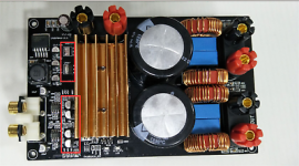
What's the difference between the blue and black?
There seems to be some extra capacitors on the black board? I have no idea.
Anyone have any thoughts on this PSU?
800W DC48V LLC Switching power supply board for amplifier PSU TPA3255 amp etc | eBay
Anyone have any thoughts on this PSU?
800W DC48V LLC Switching power supply board for amplifier PSU TPA3255 amp etc | eBay
What's the difference between the blue and black?
Found it, the black board having few extra component
Attachments
- Home
- Amplifiers
- Class D
- What is wrong with TPA3255?