hello, i can not answer, this schema is taken from here (PASS LABS CLONE - Aleph-2 PS-X1 Amplifier Power Supply PCB)10A fuse seems too high for a 600VA transformer.
A 600VA 72Vac transformer has a maximum continuous AC current into a resistive load of 8.3Aac.
If instead you connect it to a capacitor input filter, the maximum continuous DC current drops to ~ 50% to 60% of the AC rating, i.e. 4.1Adc to 5Adc
You can obtain effective protection using a close rated mains fuse in the primary circuit. The secondary fusing then becomes unnecessary.
The 0.1uF capacitors on the PSU output don't provide any useful function.
Why 3V to 4V white LEDs as indicators?
Would Green LEDs mean good to go?
J.Curl showed a control circuit for a balanced stage where he set an automatic control for each side and then added a third control to reduce the residual offset.
The F5 is similar in that the upper and lower currents are set independently. Maybe this is a case where three control circuits are required to be effective in controlling the output offset.
The F5 is similar in that the upper and lower currents are set independently. Maybe this is a case where three control circuits are required to be effective in controlling the output offset.
The F5 is similar in that the upper and lower currents are set independently. Maybe this is a case where three control circuits are required to be effective in controlling the output offset.
Are you saying, Andrew, that because the upper and lower currents are set independently - this will allow DC offset to be minimised.
Or are you saying that, just like in JC's balanced example ... a 3rd control circuit is necessary to do this (set DC offset to zero) for an F5/F5 Turbo. If so ... for us ignorant folk, what would this control circuit look like?
Thanks,
Andy
Help needed 'blow ups'
What the F""" am I doing wrong..
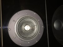
There I was listening to a bit of 'easy afternoon chillout' CD No4 so about 2 hours listening of the afternoon. Then Bang.....smoke and smell issuing from one side 'channel' of the power amp. The fuse did not blow (T4) and the other channel carried on playing. Jump to feet and off with the power. It was all to late, blown the coil out of the front of the newly aquired SAL full range driver....
This is not the first blow up Iv'e had.....errrr but this cost and may end my 25 year love affair with DIY. I am really pissed off that I can't see whats going wrong or what I'm doing wrong.
2 off 325va trainis 2x33v secondaries
48v rails
90,000uf per rail
DIY audio 5U case
250mv bias (low really:- driven by fear)
better than 5mv offset
Both bias and offset at a steady state after 4 hours on the bench prior to being pressed into service...as I recall.
Any ideas
I'll post better photos later...
What the F""" am I doing wrong..
There I was listening to a bit of 'easy afternoon chillout' CD No4 so about 2 hours listening of the afternoon. Then Bang.....smoke and smell issuing from one side 'channel' of the power amp. The fuse did not blow (T4) and the other channel carried on playing. Jump to feet and off with the power. It was all to late, blown the coil out of the front of the newly aquired SAL full range driver....
This is not the first blow up Iv'e had.....errrr but this cost and may end my 25 year love affair with DIY. I am really pissed off that I can't see whats going wrong or what I'm doing wrong.
2 off 325va trainis 2x33v secondaries
48v rails
90,000uf per rail
DIY audio 5U case
250mv bias (low really:- driven by fear)
better than 5mv offset
Both bias and offset at a steady state after 4 hours on the bench prior to being pressed into service...as I recall.
Any ideas
I'll post better photos later...
Attachments
Last edited:
Recheck builds
Wow!!!!, Tanks Zen Mod, I did miss this one, I need to recheck my F5 and F5T before the next listening session.
was there any contact between small NTC and mosfet washer ?
several times we wrote about risking with that , considering that paint on NTC can't be trusted to serve as electrical isolator
when I made F5 , NTC was in direct contact with mosfet ceramic case , not metal
This happened to me. If you are careless with the ntc when installing and removing the boards it will scratch off the insulation paint. Then sparks and smoke will happen. My thermistors are covered in heat shrink now and thermal pasted to the mosfets.
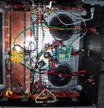
Also, in my experience accidental grounding of the ntc created a big arc burn on the mosfet washer and the ntc caught fire. Gate resistors we’re fine (yours are smoked) and it smoked the bias trim pots as well.
Did the bias run away due to the diodes? What were the heatsink temps?
Did the bias run away due to the diodes? What were the heatsink temps?
was there any contact between small NTC and mosfet washer ?
several times we wrote about risking with that , considering that paint on NTC can't be trusted to serve as electrical isolator
when I made F5 , NTC was in direct contact with mosfet ceramic case , not metal
I never knew or saw this....and will be taking steps to rectify the NTC poss problem. But I don't think this was the issue here..this is the third time Ive had blow ups.
The last time (2 months ago) just by turning the vol up to past 3:00-4:00 o'clock (no signal btw, nothing playing but everything hooked up) took out both mono blocks. Both mains fuses blow and all 8 mosfets F"""""d in both amps. Pre is a whammy....
I think on this occasion bias ran away....I'll be setting up the amps over a period of days rather than hours next time. I recall NP mentioned Pass Labs would take 'days' to set up the bias and offset thier amps....before signing off for shipping.
bias is hardly an issue , if you got it in proper temp equilibrium
what you need to triple check is oscillation - maybe is best to mount (increase) those lag caps in feedback network
Papa is Old Devil with zillion miles under the bu.....m , having entire circuit on one pcb , with controlled patterns thus capacitance of traces etc. , so he can do it without lag caps
put some 3n9-4n7 caps across R9 and R7 , be sure that preamp is flawless regarding transients and oscillation , simply because F5 is pretty much Lucky Luke fast
and - install decent speaker protection modules
something with μPC1237 will do ...... you can even make it as separate unit , with internal PSU
I would shoot with shotgun any amplifier responsible for burning my precious RCAs
Laverda
Sorry to hear about the damage due to the F5 failure. All I can say is Ouch! That bites big time$$. I guess we all are taking a chance if we use a diy amp without any protection circuits. I’ve had my v3 running for several months now without any issues. I will have to check on those thermistors now. I did not hear of this issue during my research or build. I guess that’s an issue with a 4800 post build thread that is so big you never really read everything. I think I put them directly on the fet with thermal paste but I can’t remember exactly. I had planned to add on speaker protection but haven’t found the time to do it. With a large power supply, fuses in the transformer primary just aren’t going to help much, given the energy stored in the power supply filter. I’m wondering if you have an oscillation issue. Given that you had one issue when you simply turned up your preamp, it sure sounds like either hf noise or DC from the preamp causing issues in the F5. I went with all the precautions that Nelson had suggested in the article as far as trying to prevent oscillations from being an issue and so far so good. I am getting a new arbitrary waveform generator next week and I think I will do some extensive testing of my F5s to make sure everything is stable.
Sorry to hear about the damage due to the F5 failure. All I can say is Ouch! That bites big time$$. I guess we all are taking a chance if we use a diy amp without any protection circuits. I’ve had my v3 running for several months now without any issues. I will have to check on those thermistors now. I did not hear of this issue during my research or build. I guess that’s an issue with a 4800 post build thread that is so big you never really read everything. I think I put them directly on the fet with thermal paste but I can’t remember exactly. I had planned to add on speaker protection but haven’t found the time to do it. With a large power supply, fuses in the transformer primary just aren’t going to help much, given the energy stored in the power supply filter. I’m wondering if you have an oscillation issue. Given that you had one issue when you simply turned up your preamp, it sure sounds like either hf noise or DC from the preamp causing issues in the F5. I went with all the precautions that Nelson had suggested in the article as far as trying to prevent oscillations from being an issue and so far so good. I am getting a new arbitrary waveform generator next week and I think I will do some extensive testing of my F5s to make sure everything is stable.
DC on preamp out?
I'll be checking the pre amp....DC out.
Isn’t a single 5u chassis a bit small with 48v rails? What are your heatsink temps?
After a couple hours those diodes are gonna heat up...and conduct all the time. Then you have no source resistance and boom.
Or the amp is oscillating. Or preamp DC which I kind of doubt since the whammy has an octocoupler actively trimming bias and offset but could happen.
You are not using unshielded or fancy intervonnects with some sort of network are you?
Isn’t a single 5u chassis a bit small with 48v rails? What are your heatsink temps?
Not sure but I'll be re-assessing the sink requirement...or I can just drop to lower rail voltage..to 36vdc to be safe
a couple hours those diodes are gonna heat up...and conduct all the time. Then you have no source resistance and boom.
I recorded a heat sink temp of 42c. as I recall
the amp is oscillating. Or preamp DC which I kind of doubt since the whammy has an octocoupler actively trimming bias and offset but could happen.
The pre (Whammy) has no DC as such at output...but am leaning towards oscillation
are not using unshielded or fancy intervonnects with some sort of network are you?
I use nothing special or fancy as interconnects (got over all that years ago) Just a quality phono (RCA) nor is it connected to any thing else
Last edited:
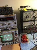
Do you have an oscilloscope and a way of generating sine/square waves? If so, I recommend you test for instability after you reach full operating temperature. Also check the preamp for ac or dc instability. Preamps in particular can oscillate with certain combinations of input level, output load etc.
Do you have an oscilloscope and a way of generating sine/square waves? If so, I recommend you test for instability after you reach full operating temperature. Also check the preamp for ac or dc instability. Preamps in particular can oscillate with certain combinations of input level, output load etc.
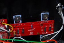
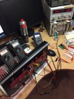
These photos were taken at the time of build and all measured well and stable. I did run on the bench to .5v bias which as you can see is drawing 2.3amps per rail this is at 32vdc as I remember:- just to see.
Square wave was good too..1v input at 10k
I was very happy and ended running the amp at 250mv of bias well below a recommended 300mv....by members.
Attachments
I am running mine at 250mv as well, at about 45volt supplies.These photos were taken at the time of build and all measured well and stable. I did run on the bench to .5v bias which as you can see is drawing 2.3amps per rail this is at 32vdc as I remember:- just to see.
Square wave was good too..1v input at 10k
I was very happy and ended running the amp at 250mv of bias well below a recommended 300mv....by members.
It does look just fine. I would turn my attention to the preamp and monitor the output while producing a square wave looking for spurious oscillations. If you have a digital scope you can easily set it up to catch any oscillations that would occur on top of the square wave. I recently caught such issues on an Aleph P that worked normally until it was hot and the input was raised above a certain point. Also, make sure the DC servo is stable and not producing any large offsets or overshoots when changing levels of audio input occur.
- Home
- Amplifiers
- Pass Labs
- F5 Turbo Builders Thread