Probably an interesting link , but very difficult to translate in Italian,
maybe in English.....
http://www.lisääbassoa.fi/4th-order-kotelo/
maybe in English.....
http://www.lisääbassoa.fi/4th-order-kotelo/
Probably an interesting link , but very difficult to translate in Italian,
maybe in English.....
http://www.lisääbassoa.fi/4th-order-kotelo/
The impedance graph on that page suggests a badly-braced box with lots of panel resonance.
although there's a lot of inherent bracing, the panels look thin http://www.xn--lisbassoa-x2aa.fi/wp-content/uploads/2013/08/30122011925.jpg
The major problem I see re those sims is that the horn is a parabolic segmented expansion due to having parallel sides, so need to do a sim based on this rather than a simple one segment hyperbolic or expo with the preferred driver and work from there unless you just want to build it as is if the sim is acceptable.
GM
I just don't understand why folks can't grasp that concept.
Ok, here goes....
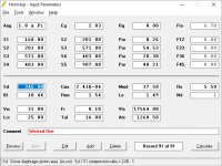
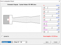
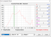
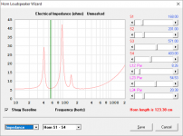
Here's a quick stab at a sim for the Wicked One. Dimensions are based on some 2D and 3D sketches I've seen around the 'net. As previously mentioned, I had to make some approximations for S3 as the "horn" has a pinch in its expansion, which I've placed at S4.
The sim suggests a resonance frequency of around 55 Hz, which in turn suggests a LF cutoff point around 38 Hz with an optimum driver. If anyone can actually do an impedance test on one of this 10" Wicked Ones, that could help to confirm how far off the model is.
If the model is correct, this alignment is not all that good for typical 10" subwoofer drivers, but it's not all that bad for some 10" pro audio drivers, like the Dayton Audio PA255-8. See images below for more details.
Attachments
If the model is correct, this alignment is not all that good for typical 10" subwoofer drivers, but it's not all that bad for some 10" pro audio drivers, like the Dayton Audio PA255-8. See images below for more details.
Note that I used the stated dimensions of the WO for 10" drivers (36" x 36 x 13.5") for the sim. If however you can shoehorn 12" drivers into the box (which might be possible, given the dimensions), it does start to get more interesting. Here is the sim, this time with the Dayton DS315 12" driver instead. Basically if the driver needs a ~2 cu.ft. box for a maximally flat vented alignment with an F3 around 38~42 Hz, it might be a good match for the WO 10" version, if the sim is correct, of course.
Attachments

First and foremost - Brian, get well soon.
Second, the Wicked One plans were once free and are still available on the wayback machine. I'm obviously not going to post a link.
Third, a modified version of the Wicked One was one of the first boxes I built back around 2006 or so. (I had built one or two boxes a couple of decades previous but those don't really count.)
I built it as a back loaded horn instead of a front loaded horn and stuck a couple of no name 8 inch drivers in it. It was a real love/hate relationship - it was useless in the house, no bass at all. I had to put it in a car mostly in the back seat and fire it into the trunk to hit 40 hz. It worked well in that configuration but ONLY in that configuration, and that configuration was obviously not feasible.
When I simulated it years ago I found a big spike of unusable efficiency above the passband and below that not much better than a simple ported box. I also didn't have any suitable crossover or dsp to take care of this type of response, I only had a 12 db/oct car audio crossover.
That box didn't last long. It was useless. But at the top of the passband it worked quite well so it prompted me to learn a thing or two about horns - so at least there's that.
in terms of the box design for the wicked one, it's just a bandpass horn any which way you skin it....driver orientation only affects volume of the rear chamber. Brian's first sets of graphs show a bit of the resonant behavior I'd assume JAG is referring to.
that said, thanks Brian for the Sim work, will be fun to play around with it a bit and see if multiple drivers, etc have any effect for the better.
that said, thanks Brian for the Sim work, will be fun to play around with it a bit and see if multiple drivers, etc have any effect for the better.
How could you fault the box if you modified it from a FLH to a BLH?
Because it's pretty much the same thing. Not exactly but close enough.
Here's how I built it. The drivers were right inside the mouth and I eliminated the panels dividing the chamber in half completely.
An externally hosted image should be here but it was not working when we last tested it.
Now here's a couple of quick models based on Brian's sim inputs. Mine doesn't match his exactly but I think that's because he used some stuffing in the flare to simulate box losses and I didn't but it's still close.
In each of the 4 pics the light grey is Brian's model.
The top row shows Brian's model converted to a ported box (black) vs original (grey).
The bottom row shows Brian's model converted to a tapped horn (black) vs original (grey).
An externally hosted image should be here but it was not working when we last tested it.
If I had mounted the drivers anywhere on the outside of the box the ported box sim would apply. And that would have changed things. But I mounted the drivers inside the mouth so the tapped horn sim applies. And the tapped horn sim is almost the same thing as the original sim. There's a bit of difference in the excursion graph but once you put the high pass on the tapped horn things will be pretty even.
Hornresp doesn't have enough segments to accurately place the mouth side tap in the sim but it's not that far off and it's the best I could do without firing up Akabak which isn't an option right now.
In the interest of full disclosure I didn't know any of this at the time, I just intuitively figured it would be fine to do it like that. It's all rather obvious now though, knowing what I know now.
I think the biggest problem with mine was the drivers I chose. I don't have specs for them (although I could measure them now) but I believe they were wildly unsuitable for this box.
I think the biggest problem with mine was the drivers I chose. I don't have specs for them (although I could measure them now) but I believe they were wildly unsuitable for this box.
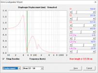
The difference in the excursion is very high below 40 Hz ,
If you are talking about my sims the excursion is not high at all once you put a required high pass filter in place.
If you are talking about my sims the excursion is not high at all once you put a required high pass filter in place.
With the W032 probably I don't need an high pass filter , has
half or less the excursion under 40 Hz ......Probably I can also equalize
the deep bass.
The front loaded horns don't necessarily need a high pass filter. The rear loaded horns and tapped horns do. And when you implement the high pass filter you will see that excursion is quite similar.
You shouldn't be using a horn below the natural low knee. Expecting the WO or WO32 to play 20 hz is insane, it's not going to happen. If you want to play 20 hz tune the horn to 20 hz.
You shouldn't be using a horn below the natural low knee. Expecting the WO or WO32 to play 20 hz is insane, it's not going to happen. If you want to play 20 hz tune the horn to 20 hz.
- Status
- This old topic is closed. If you want to reopen this topic, contact a moderator using the "Report Post" button.
- Home
- Loudspeakers
- Subwoofers
- Has anyone ever measured a Wicked One or similar brothers ?