Bad load regulation. It is only acceptable for low power, because of voltage droop and ripple when drawing current.
4 diodes don't necessarily make more noise than 2 diodes, it is not that simple.
For instance, fast recovery diodes at linear PSU is plain stupid when expecting lower diode noise.
More than one secondary winding is no big deal.
4 diodes don't necessarily make more noise than 2 diodes, it is not that simple.
For instance, fast recovery diodes at linear PSU is plain stupid when expecting lower diode noise.
More than one secondary winding is no big deal.
hiWhy is full wave voltage doubler not used more in line level audio? Only single secondary transformer is needed and two diodes. Two diodes, of whatever type, make two times less switching noise than 4 diode bridge rectifier.
Please show the schematic you are proposing?
I'll assume you actually mean using only one winding w/ 2 diodes for obtaining a floating center connection for +/- supplies. This one has poor filtering and inefficient transformer use. To get the same regulation and ripple rating as the double winding/diodes is costing more and displacing more volume E.g needs bigger capacitors and VA ratings and may have imbalance issues. Lower number of diodes doesn't make less noise! It can actually be worse depending on many factors.. proper parts, layout and wiring will have greater influence.
Last edited:
hi
I'll assume you actually mean using only one winding w/ 2 diodes for obtaining a floating center connection for +/- supplies.
Yes, that's what I ment.
The differences between a FW doubler and a FW rectifier using a winding of twice the voltage is very subtle indeed, and could be missed in a first analysis, but they do exist: in a FW rectifier, two sets of diodes replenish a single filter capacitor twice per cycle, whereas in a (so-called) FW voltage doubler, two times one diode replenish two caps once per cycle, and the cap voltages are later added.Why is full wave voltage doubler not used more in line level audio? Only single secondary transformer is needed and two diodes. Two diodes, of whatever type, make two times less switching noise than 4 diode bridge rectifier.
The result looks superficially similar, but it isn't: adding two half-wave rectifiers isn't equivalent to a true full wave rectifier.
The ripple seen by each half-wave cap is somewhat higher, and because the conduction angle is not the same, the ripple voltage is (marginally) higher (supposing of course that you use double capacity capacitors for the doubler, otherwise the comparison is unfair).
However, for low voltages, things tend to even out, because the FW rectifier has two diode drops instead of one.
A true FW doubler (without a center tap Xformer) is in theory a possibility, but in theory only: it requires 6 diodes and three capacitors, and has therefore more components and losses than all the other options.
That said, I confirm that the "Latour" doubler is an alternative worth considering (better than a center-tap FW rectifier for example) and carries only a small penalty in increased ripple and stress on the components.
The components count and voltage drop is also minimal.
i use voltage doublers a lot, and since i make my own traffos,
design and builds are not as meticulous as having high voltage winding...
ss rectifiers are dirt cheap nowadays, i use them a lot too...
transformer utilization is 30% better than the traditional center tapped FW rectifiers...
design and builds are not as meticulous as having high voltage winding...
ss rectifiers are dirt cheap nowadays, i use them a lot too...
transformer utilization is 30% better than the traditional center tapped FW rectifiers...
Depends on your definition and POV. It's not when you are buying the parts.transformer utilization is 30% better than the traditional center tapped FW rectifiers...
A voltage doubler is conducting half the time, so the higher I peak comes to play, reducing XFMR regulation for a given VA rating. Most times this is an auxiliary winding on some huge iron so essentially a don't care in power amps. Standard wall warts with 2 wire plugs are used to shift safety regulations out of the box, but they still must be sized larger.. Everything is a tradeoff.

Last edited:
A doubler conducts twice/cycle, just like a rectifier bridge.
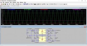
The transformer's peak current and utilization is mostly unaffected, as shows this simmed example.
The parameters and values have been scaled to allow for a fair comparison between the two solutions:
The transformer's peak current and utilization is mostly unaffected, as shows this simmed example.
The parameters and values have been scaled to allow for a fair comparison between the two solutions:
Attachments
For instance, fast recovery diodes at linear PSU is plain stupid when expecting lower diode noise.
In one voltage doubler used for preamplifier I used two Schotky diodes. I did not notice any degradation of sound whatsoever. There is many who believe that fast diodes are better for audio. Can you point me to some source where there is some measurements proving that fast diodes produce more interference in audio band than standard silicone diodes?
Personally? Fast diodes are cool… but ultimately EVERY precision amplifier should have a regulated power supply section. Seriously. CLC in front of regulator ("X") in a CLCXC configuration for very low output impedance and excellent ripple suppression.
See that "L" there? When situated mechanically very close to the rectifiers and first condenser, it also suppressed just about ALL of the RF that designers who praise fast diodes worry over. And that goats, is the trick, isn't it?
Transform → rectify → suppress noise → store in C1, → suppress RF and HF ripple with L1 → store more in C2 to remove MORE ripple → regulated down with enough VDROP to easily fit the whole power-use worst case cycle-to-cycle drop, and then → C3 as an impedance killing reservoir.
With careful PCB layout on a separate little card, all you get out is reliable quiet DC. And the secondary benefit is that is also independent of the mains fluctuations. Win-Win-Win!
GoatGuy
The parameters and values have been scaled to allow for a fair comparison between the two solutions:
This is the perfectly balanced case E.g. simplified model with a single load.
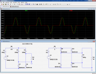
 Compare the worst cases, with unbalanced dual loads.
A good many switch mode supplies use full wave doublers on the mains when operating off US 120 volts. Same supply with one jumper change turns into a standard full wave (with 4 diodes) that runs off 240V.
It's a lot harder on the rectifier and caps in 120 volt mode (which is why the caps like to bulge and vent), and the raw 330V DC voltage sags more under load.
It's a lot harder on the rectifier and caps in 120 volt mode (which is why the caps like to bulge and vent), and the raw 330V DC voltage sags more under load.
I came up with this combination power supply for a guitar amp project. The power supply is in the upper right of the schematic.
The power transformer is a 100 VA 120 to 120 volt isolation transformer.
Diodes D1 through D4, C24 R61 and C23 form a full wave bridge rectifier and filter network. It supplies 165 volts DC at 120 to 170 mA for the tube heaters (wired in series) and the output tube screen grids.
Diodes D5 through D8 (with help from D1 and D2) form a full wave voltage doubler that supplies about 330 volts of B+ for the 5 tube amp. The amp makes about 20 watts at the edge of clipping and nearly 30 at full crank.
The preamp tubes are 26AQ6 / UCC85 and the output tubes are 45B5 / UL84. Note that the UL84 is NOT a 45 volt EL84. It is a 45 volt 6CW5 / EL86.
The design had several experiments on one PC board, some of which did not work (the mosfet controlled cathode bypass caps). There was far too much gain in the preamp section even for a full metal racket amp, so some of the mosfet buffers and one entire gain stage have been ripped out. The rest still lives on and awaits some more tweaking and a new PCB layout with far less parts.
The power supply however, has been rock solid.
Attachments
Personally, I prefer to choose rectifier diodes with gigantic amounts of excess safety margin. The chipamp PSU linked below, for example, has a maximum continuous output current of only 3.5 amperes, yet it contains a 4-diode bridge built with diodes rated for 30 amps continuous current & 300A surge. That's just my preference.
Other people like to squeeze the parts cost very aggressively, and use the lowest-rated (lowest cost) diodes they can get away with.
It might be worth noting that when comparing a two diode "voltage doubler" power supply, to a four diode "bridge rectifier" power supply,
Common sense and engineering mathematics agree: Spreading the work across four diodes instead of two diodes, reduces each diode's workload.
_
Other people like to squeeze the parts cost very aggressively, and use the lowest-rated (lowest cost) diodes they can get away with.
It might be worth noting that when comparing a two diode "voltage doubler" power supply, to a four diode "bridge rectifier" power supply,
If the two supplies provide the same output voltages, at the same continuous output currents,
The diodes in the two-diode supply, work a lot harder than the diodes in the bridge rectifier supply. Average diode current is double, and diode power dissipation (measured on a timescale of 1 second) is more than 2X. You might need to use beefier diodes in a two diode "voltage doubler" than in a comparable four diode "bridge rectifier" supply.
Common sense and engineering mathematics agree: Spreading the work across four diodes instead of two diodes, reduces each diode's workload.
_
Last edited:
I agree.
The cost is mostly in the transformer and the reservoir caps.
Dual secondary windings is the same cost as a center tap winding.
Spreading the work to more diodes.... Why not going from center tap with single rectifier bridge to dual windings with dual rectifier bridges ?
That is more diode voltage drop, but is grounding better and there is no issue when windings or loads are not perfectly balanced between the plus and minus supplies.
Last edited:
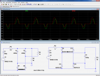
Unbalanced loads will of course subject the transformer to DC current, which is not advisable, but the peak currents remain exactly as expected.This is the perfectly balanced case E.g. simplified model with a single load.
This scheme is obviously not usable for asymetric loads, but it still covers a good number of real-life situations
Attachments
- Home
- Amplifiers
- Power Supplies
- Why is full wave voltage doubler not used more?